Navigation
Related
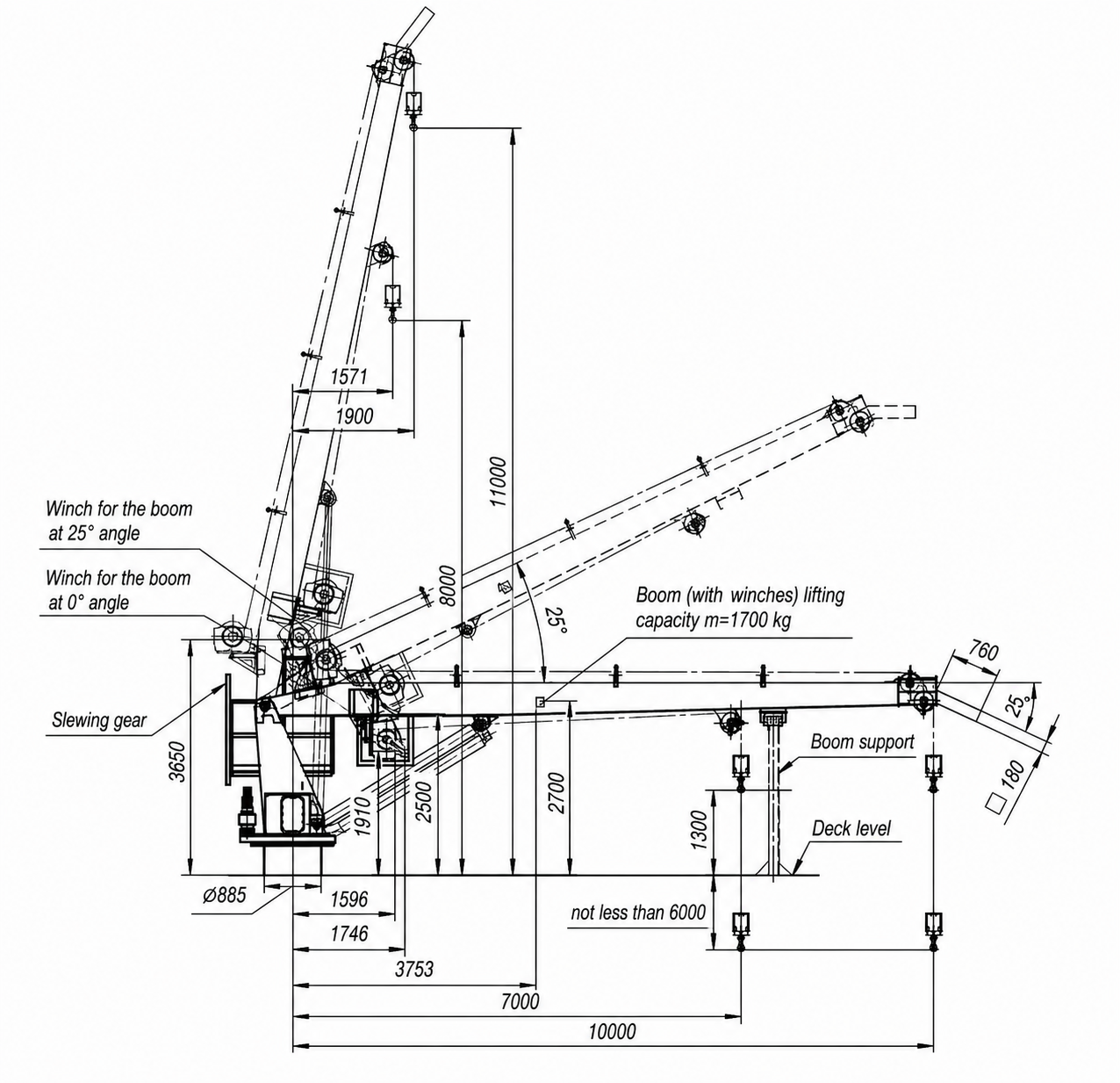
The stiff boom crane is designed for handling aids to navigation (AtoN) in sea states, as well as for recovering navigation buoys, fenders, and anchors, and performing onboard cargo operations.
Crane operating conditions:
Crane stowed conditions:
The stiff boom crane is utilized for:
Stiff Boom Cranes: Reliable Operation in Harsh Marine Environments
The Value of Simplicity in Marine Machinery
Cranes have evolved beyond basic lifting devices into integral parts of complex shipboard systems, where mechanics, hydraulics, and crew experience operate in unison. Within this framework, the stiff boom crane demonstrates its core value: simple kinematics ensure predictable and transparent system behavior for the operator.
Operator Ergonomics and Predictable Trajectory
The stiff boom design minimizes the number of joints and potential failure points, ensuring intuitive control. This approach prioritizes practicality over unnecessary complexity—delivering reliable and straightforward performance under actual operating conditions rather than abstract design perfection.
Marine Environment Dynamics and Requirements
Offshore lifting operations entail continuous interaction with waves, wind, and vessel motions. Structural and operational designs focus on maintaining stability under these conditions, where boom configuration directly influences load predictability. In such environments, field experience often outweighs theoretical calculations.
Long-Term Operation and Environmental Safety
Modern engineering mandates both extended service life and minimized environmental risks. Key design and operational criteria include safe emergency operation and robust component protection against aggressive marine environments. This approach reduces incident probability and enhances cost efficiency.
OEM Expertise as Part of the Solution
Selecting shipboard equipment increasingly depends on the manufacturer’s field expertise alongside structural functionality. Izhora Hydrosystems LLC manufactures stiff boom cranes engineered specifically for marine operations and demanding crew working conditions. This approach combines equipment reliability with high serviceability and dependable performance in harsh environments.
Procurement Selection Note
When prioritizing seamless crew integration and minimized downtime, selecting a design with predictable performance characteristics is highly justified. Consequently, the stiff boom crane remains a preferred option in practical applications where rapid deployment and daily operational reliability are paramount.
| Item Description | Qty |
| Stiff boom crane | 1 pc. |
| Pedestal | 1 pc. |
| Housing | 1 pc. |
| Boom assembly | 1 pc. |
| Platform | 1 pc. |
| Winch base | 2 pcs. |
| Winch | 2 pcs. |
| Hook No. 1 | 1 pc. |
| Hook No. 2 | 1 pc. |
| Interface assembly | 1 set |
| Cradle for stowing the boom in stowed position | 1 pc. |
| Hydraulic cylinder | 1 pc. |
| Hook block | 1 pc. |
| Boom rest | 1 pc. |
| Floodlight installation | 1 set |
| Inclinometer installation | 1 set |
| Control panel cover | 1 pc. |
| Access hatch | 1 pc. |
| Warning light installation | 1 set |
| Acoustic horn station | 1 set |

| Parameter | Value |
| SWL, Hook No. 1 (harbor conditions) | max. 3,500 kg (outreach 7 m);min. 1,500 kg (outreach 10 m) |
| SWL, Hook No. 2 (harbor conditions) | 3,500 kg (outreach 7 m) |
| Total crane capacity during simultaneous dual hook operation | max. 3,500 kg |
| SWL, Hook No. 1 (sea state conditions) | max. 2,800 kg (7 m); min. 1,500 kg (10 m) |
| SWL, Hook No. 2 (sea state conditions) | 2,900 kg (7 m) |
| Total crane capacity during simultaneous dual hook operation | max. 2,900 kg |
| Outreach, Hook No. 1 | 1.9–10.0 m |
| Outreach, Hook No. 2 | 1.6–7.0 m |
| Hoisting/lowering speed | 0–20 m/min |
| Lowering depth below slewing bearing | min. 6 m |
| Winch drive | Hydraulic |
| Wire rope diameter | 19.5 mm |
| Slewing angle | Continuous |
| Slewing speed (unloaded) | max. 0.8 rpm |
| Slewing drive | Hydraulic |
| Luffing time | max. 60 s |
| Power supply | 3-phase, 380 V, 50 Hz, IT net (without neutral wire) |
| Control system | Local control panel (on the slewing platform);Portable remote control panel with 10m cable |
| Control cabinet | Freestanding |
| Hydraulic power unit (HPU) | Integrated into the crane housing |
Standard OEM spare parts kit for 5-year operation.
| Document Description | Qty |
| Technical data sheet (Passport) | 1 |
| Operating manual | 1 |
| Certificates | 1 |
RS (Russian Maritime Register of Shipping) and Gostechnadzor of the Armed Forces of the RF certificates.
The crane design ensures compliance with occupational health and safety standards during installation, operation, maintenance, and repair.
Component failure, power supply loss, or voltage fluctuations outside international standard limits, as well as hydraulic pressure drops or surges, shall not result in an emergency situation.
All safety devices are calibrated and sealed.
Each hoisting and luffing mechanism is equipped with hydraulic counterbalance valves.
The stiff boom crane features automatic cut-off devices triggered by:
a) Overload exceeding 10% of the rated capacity under harbor conditions, and any overload exceeding the rated capacity under sea states up to sea state 3 inclusive;
б) Hook and boom reaching their upper and lower limit positions.
Following safety device activation, movement in the reverse direction remains functional.
The wire rope safety factor is 5.0.
The electric drive circuit incorporates the following protection types:
a) Low-voltage protection preventing automatic motor restart upon power restoration after a black-out;
б) Motor overload protection;
в) Interlock system preventing motor start via interlock contacts.
The pump unit power circuits are equipped with soft-starters to limit inrush currents.
To prevent environmental pollution by hydraulic fluid during system filling, draining, or leakage discharge, the fluid reservoirs are equipped with shut-off valves.
The crane is controlled from the operator platform or via a chest-pack type portable remote control panel with a 10-meter cable.
The operator platform is side-mounted on the crane. Access is provided via a sliding ladder. A slewing interlock is active when the ladder is in its lowermost position. The operator platform features a buoy impact protection guard.
All crane control elements feature labels in Russian.
The control system provides step-less speed regulation for all crane movements from zero to maximum, as well as simultaneous operation of working motions (with reduced maximum speeds).
Connection point for the remote control panel is provided.
The crane control system incorporates a selector switch on the operator platform with settings: “1. Harbor conditions – 0 – 2. Sea state 3”.
Emergency Stop push buttons (red) are installed on both the operator platform and the remote control panel to isolate main electric drive circuits and apply brakes to all crane motion mechanisms. “Running” and “Common Fault” indicator lights are also provided.
Control handles for the main crane mechanisms are equipped with spring-return to neutral.
The crane features a 500 W floodlight and an acoustic horn. Control buttons for the floodlight and horn are located on the operator platform and duplicated on the remote control panel.
Hydraulic motor equipped with a counterbalance valve, planetary gearbox, and multi-disc brakes. The winch drum features Lebus-type grooving.
The wire rope is rotation-resistant, galvanized, with a minimum breaking load of 5.0 x SWL.
Rope sheaves are fitted with retaining guards to prevent the wire rope from jumping out of the grooves.
Hooks on the cargo block are of the enclosed type and feature safety latches to prevent rigging or slings from detaching from the hook throat.
4.5 Hydraulic System
The hydraulic system consists of an oil tank, a hydraulic power unit (HPU) driven by an individual electric motor, high-pressure filters, and marine-grade valve blocks with pressure relief valves (valves are located at the operator platform).
The pump unit is located inside the slewing column, and the electric motor is mounted inside the crane base.
The HPU features a high-grade 3-phase motor:
Voltage: 3 x 380 V, 50 Hz
Power: approx. 35 kW
Protection class: IP56
For the hoisting and slewing mechanisms, a hand pump is provided for emergency load lowering in the event of a main power failure. The hand pump is engaged by turning a selector valve.
Continuous slewing (unlimited angle, utilizing an integrated electrical slip ring assembly). Full slewing capability under safe working load (SWL) at 8° heel and 2° trim. The system incorporates a marine-grade ball-bearing slewing ring and two hydraulic slewing motors equipped with pressure relief valves, planetary gearboxes, and multi-disc brakes.
Double-acting luffing cylinder featuring a chrome-nickel plated piston rod. The cylinder is fitted with counterbalance valves for load holding. A buoy impact protection guard is mounted on the cylinder.
The crane base (pedestal adapter) is designed for welding to the vessel deck structure. The bottom edge of the adapter shell is chamfered for weld preparation at the shipboard foundation interface. All foundation fasteners for securing the crane to the adapter are included in the scope of supply.
Izhora Hydrosystems LLC
12 months from the date of shipment, unless otherwise specified by the contract.
Related
Personal Data Processing Policy
1. General provisions
This Personal data processing Policy is compiled in accordance with the requirements of Federal Law No. 152-FZ dated 27.07.2006 “On Personal Data” (hereinafter referred to as the Personal Data Law) and defines the procedure for processing personal data and measures to ensure the security of personal data taken by Izhora Hydrosystems Co. Ltd (hereinafter referred to as the Operator).
1.1. The Operator sets as its most important goal and condition for the implementation of its activities the observance of the rights and freedoms of man and citizen in the processing of his personal data, including the protection of the rights to privacy, personal and family secrets.
1.2. This Operator’s policy regarding the processing of personal data (hereinafter referred to as the Policy) applies to all information that the Operator can receive about website visitors https://i-hydro.ru .
2. Basic concepts used in the Policy
2.1. Automated processing of personal data — processing of personal data using computer technology.
2.2. Blocking of personal data — temporary termination of processing of personal data (except in cases where processing is necessary to clarify personal data).
2.3. Website – a set of graphic and informational materials, as well as computer programs and databases that ensure their availability on the Internet at a network address https://i-hydro.ru .
2.4. Personal data information system — a set of personal data contained in databases and information technologies and technical means that ensure their processing.
2.5. Depersonalization of personal data — actions as a result of which it is impossible to determine, without the use of additional information, the identity of personal data to a specific User or other subject of personal data.
2.6. Personal data processing — any action (operation) or set of actions (operations) performed with or without the use of automation tools with personal data, including collection, recording, systematization, accumulation, storage, clarification (updating, modification), extraction, use, transfer (distribution, provision, access), depersonalization, blocking, deletion, destruction of personal data.
2.7. Operator — a state body, municipal body, legal entity or individual, independently or jointly with other persons organizing and /or processing personal data, as well as determining the purposes of processing personal data, the composition of personal data to be processed, actions (operations) performed with personal data.
2.8. Personal data — any information related directly or indirectly to a specific or identifiable User of the Website https://i-hydro.ru .
2.9. Personal data authorized by the subject of personal data for distribution — personal data to which an unlimited number of persons have access by the subject of personal data by giving consent to the processing of personal data authorized by the subject of personal data for distribution in accordance with the procedure provided for by the Law on Personal Data (hereinafter — personal data authorized for distribution).
2.10. User — any visitor to the website https://i-hydro.ru .
2.11. Provision of personal data — actions aimed at disclosure of personal data to a certain person or a certain circle of persons.
2.12. Dissemination of personal data — any actions aimed at disclosure of personal data to an indefinite circle of persons (transfer of personal data) or familiarization with personal data of an unlimited circle of persons, including the publication of personal data in the media, placement in information and telecommunications networks or providing access to personal data in any other way.
2.13. Cross—border transfer of personal data is the transfer of personal data to the territory of a foreign state to the authority of a foreign state, a foreign individual or a foreign legal entity.
2.14. Destruction of personal data — any actions as a result of which personal data is permanently destroyed with the impossibility of further restoration of the content of personal data in the personal data information system and/or the material carriers of personal data are destroyed.
3. Basic rights and obligations of the Operator
3.1. The Operator has the right to:
— receive reliable information and/or documents containing personal data from the subject of personal data;
— if the personal data subject withdraws consent to the processing of personal data, as well as sending a request to terminate the processing of personal data, the Operator has the right to continue processing personal data without the consent of the personal data subject if there are grounds specified in the Law on Personal Data;
— independently determine the composition and list of measures necessary and sufficient to ensure the fulfillment of obligations provided for by the Law on Personal Data and regulatory legal acts adopted in accordance with it, unless otherwise provided by the Law on Personal Data or other federal laws.
3.2. The Operator is obliged to:
— to provide the subject of personal data, at his request, with information concerning the processing of his personal data;
— organize the processing of personal data in accordance with the procedure established by the current legislation of the Russian Federation;
— respond to requests and requests from personal data subjects and their legal representatives in accordance with the requirements of the Personal Data Law;
— to inform the authorized body for the protection of the rights of personal data subjects at the request of this body of the necessary information within 10 days from the date of receipt of such a request;
— publish or otherwise provide unrestricted access to this Policy regarding the processing of personal data;
— take legal, organizational and technical measures to protect personal data from unauthorized or accidental access to them, destruction, modification, blocking, copying, provision, dissemination of personal data, as well as from other illegal actions with respect to personal data;
— stop the transfer (distribution, provision, access) of personal data, stop processing and destroy personal data in the manner and cases provided for by the Law on Personal Data;
— perform other duties provided for by the Law on Personal Data.
4. Basic rights and obligations of personal data subjects
4.1. Personal data subjects have the right to:
— receive information concerning the processing of his personal data, except in cases provided for by federal laws. The information is provided to the personal data subject by the Operator in an accessible form, and it should not contain personal data related to other personal data subjects, except in cases where there are legitimate grounds for disclosure of such personal data. The list of information and the procedure for obtaining it is established by the Law on Personal Data;
— require the operator to clarify his personal data, block or destroy them if the personal data are incomplete, outdated, inaccurate, illegally obtained or are not necessary for the stated purpose of processing, as well as take measures provided by law to protect their rights;
— to put forward a condition of prior consent when processing personal data in order to promote goods, works and services on the market;
— to revoke consent to the processing of personal data, as well as to send a request to terminate the processing of personal data;
— appeal to the authorized body for the protection of the rights of personal data subjects or in court against illegal actions or inaction of the Operator when processing his personal data;
— to exercise other rights provided for by the legislation of the Russian Federation.
4.2. Personal data subjects are obliged to:
— provide the Operator with reliable data about themselves;
— inform the Operator about the clarification (update, change) of their personal data.
4.3. Persons who have provided the Operator with false information about themselves or information about another personal data subject without the latter’s consent are liable in accordance with the legislation of the Russian Federation.
5. Principles of personal data processing
5.1. The processing of personal data is carried out on a legal and fair basis.
5.2. The processing of personal data is limited to the achievement of specific, predetermined and legitimate goals. Processing of personal data incompatible with the purposes of personal data collection is not allowed.
5.3. It is not allowed to combine databases containing personal data, the processing of which is carried out for purposes incompatible with each other.
5.4. Only personal data that meet the purposes of their processing are subject to processing.
5.5. The content and volume of the processed personal data correspond to the stated purposes of processing. Redundancy of the processed personal data in relation to the stated purposes of their processing is not allowed.
5.6. When processing personal data, the accuracy of personal data, their sufficiency, and, if necessary, relevance to the purposes of personal data processing is ensured. The Operator takes the necessary measures and/or ensures that they are taken to delete or clarify incomplete or inaccurate data.
5.7. The storage of personal data is carried out in a form that allows determining the subject of personal data, no longer than the purposes of personal data processing require, unless the storage period of personal data is established by federal law, an agreement to which the subject of personal data is a party, beneficiary or guarantor. The processed personal data is destroyed or depersonalized upon achievement of the processing goals or in case of loss of the need to achieve these goals, unless otherwise provided by federal law.
| Purpose of processing | Informing the User by means of voice communication and e-mail |
|---|---|
| Personal data |
|
| Legal grounds |
|
| Types of personal data processing |
|
7. Terms of personal data processing
7.1. The processing of personal data is carried out with the consent of the personal data subject to the processing of his personal data.
7.2. The processing of personal data is necessary to achieve the goals stipulated by an international agreement of the Russian Federation or a law, to carry out the functions, powers and duties assigned to the operator by the legislation of the Russian Federation.
7.3. The processing of personal data is necessary for the administration of justice, the execution of a judicial act, an act of another body or official subject to execution in accordance with the legislation of the Russian Federation on enforcement proceedings.
7.4. The processing of personal data is necessary for the execution of a contract to which the personal data subject is a party or beneficiary or guarantor, as well as for the conclusion of a contract on the initiative of the personal data subject or a contract under which the personal data subject will be a beneficiary or guarantor.
7.5. The processing of personal data is necessary to exercise the rights and legitimate interests of the operator or third parties or to achieve socially significant goals, provided that the rights and freedoms of the personal data subject are not violated.
7.6. Personal data is processed, access to which is granted to an unlimited number of persons by the subject of personal data or at his request (hereinafter referred to as publicly available personal data).
7.7. Personal data subject to publication or mandatory disclosure in accordance with federal law is processed.8. Procedure for the collection, storage, transfer and other types of personal data processing
The security of personal data processed by the Operator is ensured through the implementation of legal, organizational and technical measures necessary to fully comply with the requirements of current legislation in the field of personal data protection.
8. Procedure for the collection, storage, transfer and other types of personal data processing
The security of personal data processed by the Operator is ensured through the implementation of legal, organizational and technical measures necessary to fully comply with the requirements of current legislation in the field of personal data protection.
8.1. The Operator ensures the safety of personal data and takes all possible measures to exclude access to the personal data of unauthorized persons.
8.2. The User’s personal data will never, under any circumstances, be transferred to third parties, except in cases related to the implementation of current legislation or if the subject of personal data has given consent to the Operator to transfer data to a third party to fulfill obligations under a civil contract.
8.3. In case of inaccuracies in personal data, the User can update them independently by sending a notification to the Operator to the Operator’s email address
contact@i-hydro.ru
8.4. The period of processing of personal data is determined by the achievement of the purposes for which personal data was collected, unless another period is provided for by the contract or current legislation..
The User can withdraw his consent to the processing of personal data at any time by sending a notification to the Operator via e-mail to the Operator’s e-mail address contact@i-hydro.ru marked “Withdrawal of consent to the processing of personal data”.
8.5. All information collected by third-party services, including payment systems, means of communication and other service providers, is stored and processed by these persons (Operators) in accordance with their User Agreement and Privacy Policy. The subject of personal data and/or with the specified documents. The Operator is not responsible for the actions of third parties, including the service providers specified in this paragraph.
8.6. The prohibitions established by the subject of personal data on the transfer (except for granting access), as well as on the processing or processing conditions (except for obtaining access) of personal data permitted for distribution, do not apply in cases of processing of personal data in the state, public and other public interests defined by the legislation of the Russian Federation.
8.7. When processing personal data, the Operator ensures the confidentiality of personal data.
8.8. The Operator stores personal data in a form that allows determining the subject of personal data, no longer than the purposes of personal data processing require, unless the period of personal data storage is established by federal law, an agreement to which the subject of personal data is a party, beneficiary or guarantor.
8.9. The condition for the termination of personal data processing may be the achievement of the purposes of personal data processing, the expiration of the consent of the personal data subject, the withdrawal of consent by the personal data subject or the requirement to terminate the processing of personal data, as well as the identification of unlawful processing of personal data.
9. List of actions performed by the Operator with the received personal data
9.1. The Operator collects, records, systematizes, accumulates, stores, clarifies (updates, changes), extracts, uses, transfers (distribution, provision, access), depersonalizes, blocks, deletes and destroys personal data.
9.2. The Operator performs automated processing of personal data with or without receiving and/or transmitting the received information via information and telecommunication networks.
10. Cross-border transfer of personal data
10.1. Prior to the start of cross-border transfer of personal data, the Operator is obliged to notify the authorized body for the protection of the rights of personal data subjects of its intention to carry out cross-border transfer of personal data (such notification is sent separately from the notification of the intention to process personal data).
10.2. Before submitting the above notification, the Operator is obliged to receive relevant information from the authorities of a foreign state, foreign individuals, foreign legal entities to whom the cross-border transfer of personal data is planned.
11. Confidentiality of personal data
The operator and other persons who have gained access to personal data are obliged not to disclose to third parties and not to distribute personal data without the consent of the subject of personal data, unless otherwise provided by federal law.
12. Final provisions
12.1. The User can receive any clarifications on issues of interest concerning the processing of his personal data by contacting the Operator via e-mail
contact@i-hydro.ru
12.2. This document will reflect any changes to the personal data processing policy by the Operator. The policy is valid indefinitely until it is replaced by a new version.
12.3. The current version of the Policy is freely available on the Internet at https://i-hydro.ru .