Navigation
Related
Categories & Industries

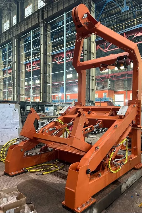
Hydraulic rescue boat davits are a core focus for our company. Their drive system ensures smooth and controlled launching and recovery even in stormy conditions, combining high power with compact dimensions and jerk-free operation. We offer various types of davits to our customers: A-frame, slewing arm, overhead, and telescopic models.
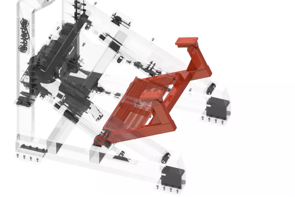
The A-Frame davit model is designed for launching boats weighing up to 30 kN. The structure includes keel blocks for secure boat fixation in the stowed position and is actuated by two hydraulic cylinders powered by an external pump unit. The scope of supply includes an external hydraulic power unit and a separate ladder for boat access.
Loading model
(highlighted in orange)
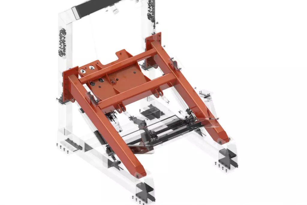
The frame is a welded steel structure with flanges that serves as a universal base for the entire davit. The winch is mounted onto it, and the structure itself can rotate around a horizontal axis in the subframe’s bearing support, ensuring stable and reliable operation of all mechanisms.
(highlighted in orange)
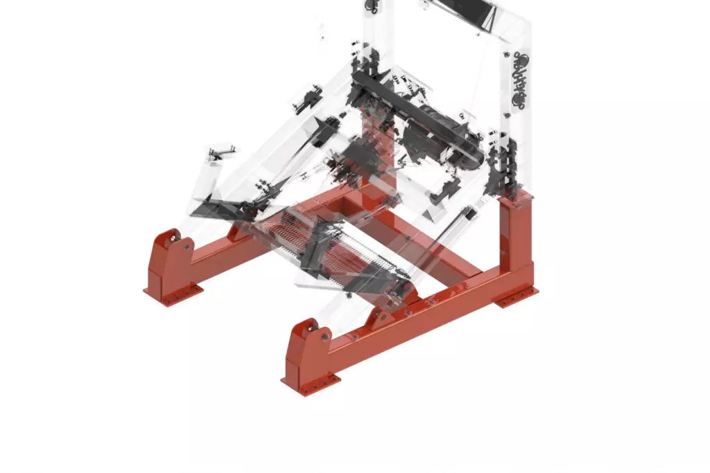
The subframe is a welded steel structure with flanges. It serves as the foundation for mounting the davit mechanisms and ensures their secure attachment to the vessel’s deck.
(highlighted in orange)
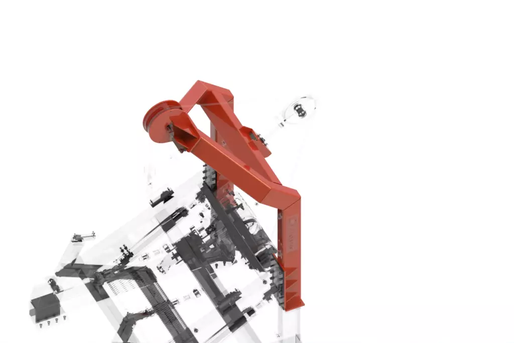
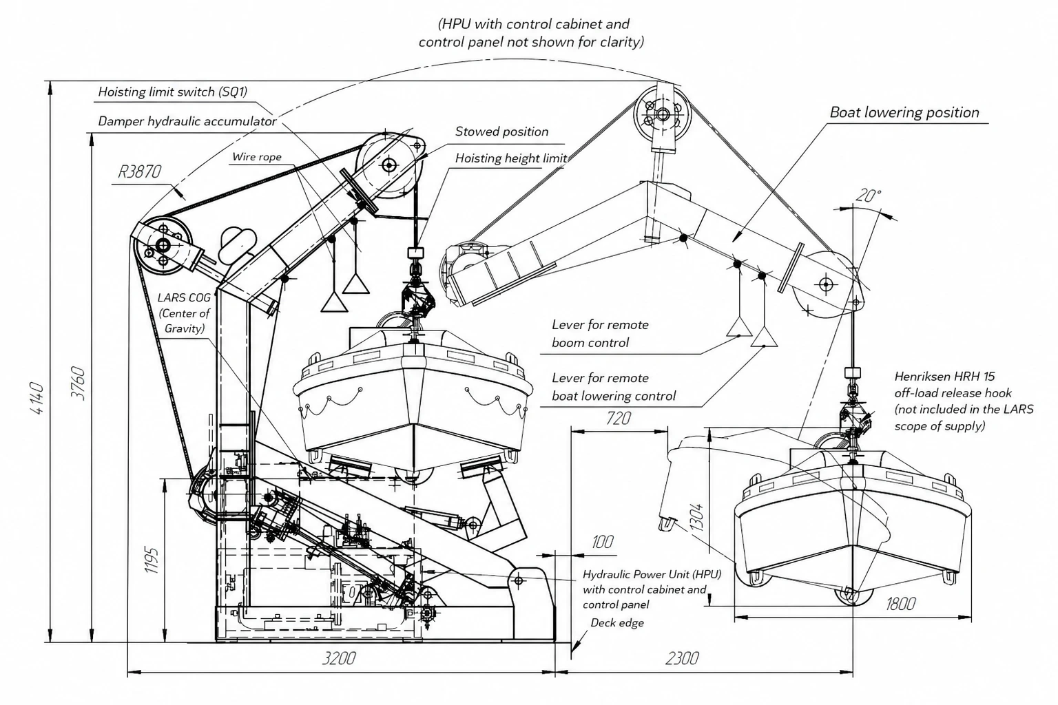
The A-frame is a welded steel structure. It is flange-mounted to the main frame and rotates with it around a horizontal axis, enabling the rescue boat to be extended overboard. The frame houses all essential control and safety components: a fall sheave, a damper, remote control rope blocks, a hoisting limit switch, and anti-slack/rope-retainer mechanisms.
(highlighted in orange)
Hydraulic cylinders with an integrated control manifold are designed for the smooth luffing of the A-frame with the boat overboard and its subsequent recovery to the stowed position.
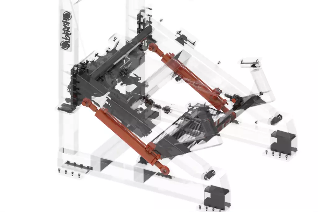
(highlighted in orange)
The keel blocks are a welded structure with support elements. They are attached to the subframe via a bearing assembly and are designed for the secure fixation of the rescue boat in the stowed position. Together with the linkage system, the keel blocks also limit the A-frame’s outboard luffing angle, ensuring operational safety.
(highlighted in orange)
The winch is designed for the launching and recovery of the rescue boat. Its hydraulic drive is managed via a local control console during recovery. Gravity-lowering of the boat (in life-saving mode) can be performed either locally at the davit or remotely—directly from within the boat.
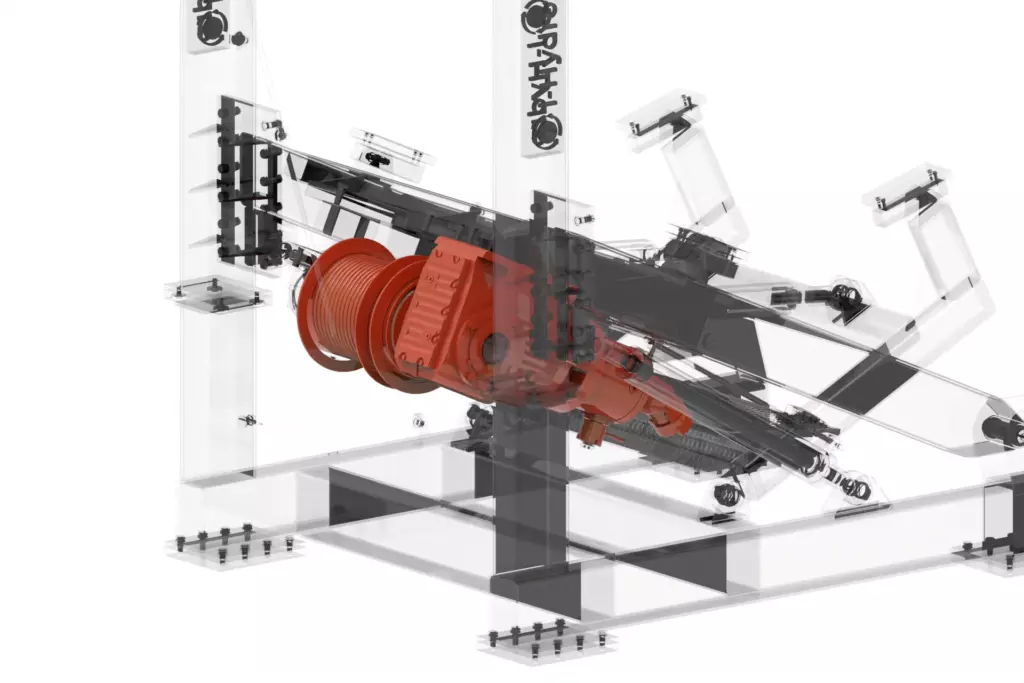
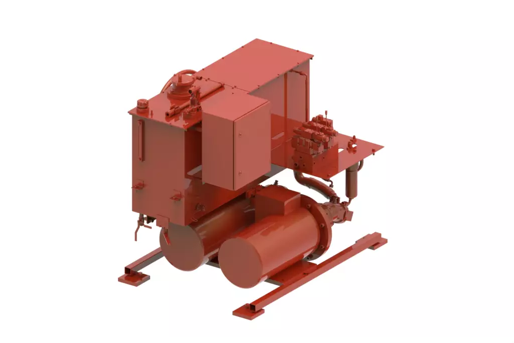
(highlighted in orange)
The hydraulic power unit, designed as a separate electric-drive module, powers all the davit actuators. It includes hydro-pneumatic accumulators that guarantee device control even in the event of a power failure.
(highlighted in orange)
For the crew to board the craft, the davit is equipped with a stationary ladder. It is supplied as a separate unit, allowing it to be relocated if necessary for the convenience of the personnel.
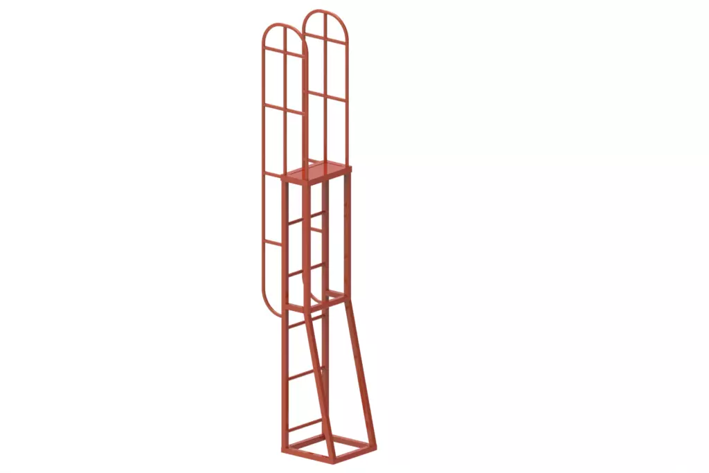
The standard configuration also includes the following documentation provided with the davit:
| Document | Quantity |
|---|---|
| Product Data Sheet | 1 |
| Installation, Commissioning, and Adjustment Manual | 1 |
| Operating Manual | 1 |
| Onboard Test Program and Methodology | 1 |
| Declaration of Materials (DM) | 1 |
| Supplier’s Declaration of Conformity (SDoC) | 1 |
Ocean Rescue Swings: How a Marine Boat Launching System Works
Lowering a heavy boat from the deck into raging waters is a task that only seems simple at first glance. At sea, everything is in motion: the vessel heels at 20 degrees, the bow pitches up or, conversely, plunges down. And inside the boat are people trusting that the equipment will not fail.
It is for these extreme conditions that this device is engineered. Essentially, it is a powerful “crane” that can not only gently lower and raise a 3-ton load but also do so even if the vessel loses power.
Three-Ton Operations in Saltwater
Our device is a true heavyweight. It is capable of raising and lowering loads of up to 3,000 kg (30 kN)—the exact weight of a rescue boat fully loaded with crew and gear.
The structure itself weighs nearly 4 tons, and when the hydraulic power unit is added, it reaches 5.5 tons. Its dimensions are proportionate: approximately 4 meters in height and nearly the same in length and width. This is not just a piece of hardware, but a complex mechanism designed to operate in any weather (climate version OM1—meaning “all climatic zones, including the tropics and the cold”).
Why It Is More Complex Than It Seems
The primary challenge when launching a boat is not the weight, but the motion. A vessel can heel up to 20 degrees or pitch up to 10 degrees. A standard crane would refuse to operate under such conditions: the load would begin to swing, wire ropes could fray against the edges, and mechanisms might jam.
Therefore, the design is ingenious. The entire A-frame with the winch can rotate not only up and down but also along with the frame around a horizontal axis. This allows the mechanism to “adapt” to the vessel’s position, dampening abrupt movements.
What It Is Made Of
To ensure the steel doesn’t crack from fatigue in salt water, engineers selected specialized grades—E36 and 09G2S. These aren’t just “pieces of iron” but high-strength alloys used in shipbuilding. All load-bearing parts—the frame, A-frame, keel blocks, and even the hydraulic cylinders—are welded from these materials.
Speaking of welding, the seams here are extraordinary: each one is inspected with surgical precision—first visually, and then the most critical ones are X-rayed or ultrasonically tested. No microcracks allowed.
The Main Protagonist: The A-Frame and Its “Muscles”
The A-frame is a long metal arm that extends the boat overboard. It is mounted to the frame and controlled by two powerful hydraulic cylinders. Imagine two giant “syringes” with pistons pushing the frame up and down. Inside them is oil under pressure, with flow managed by a specialized hydraulic manifold.
When the boat needs to be stowed (returned to the “stowed” position), the cylinders act in reverse, pulling the structure back onto the deck. To prevent the A-frame from accidentally extending too far overboard, it is secured by special turnbuckle stays—adjustable “leashes” that limit the luffing angle.
The Damper: A Clever Shock Absorber
The most interesting feature is a device called a damper. This is a separate hydraulic cylinder that, in its normal state, stands with its rod extended like a vigilant sentinel. When a wave abruptly jerks the boat, the entire impact load is transmitted to the wire rope. This is where the damper comes into play: it smoothly “swallows” the shock, preventing it from damaging the mechanisms. It’s like a car’s shock absorber, but designed for a wire rope suspension system.
The Heart of the System: The Winch and Its Brake
The winch is perhaps the most critical component. Hidden within it are a hydraulic motor, a powerful gearbox, and a specialized brake. Why is a brake necessary? While the hydraulics handle the boat’s recovery, lowering is done autonomously under its own weight—a process known as “gravity lowering.”
The speed must be regulated with surgical precision: too fast, and the boat with its crew will slam into the water; too slow, and it could be bashed against the hull. The lowering speed (from 40 to 60 meters per minute) is controlled by that very brake. The controls are designed with a failsafe: the moment the operator releases the handle, the descent stops instantly.
Manual Mode and the “Red Button”
The sea is unpredictable. If the vessel loses power, the 1,650 kg hydraulic power unit will stop pumping oil. However, the designers have accounted for this.
First, the HPU includes hydro-pneumatic accumulators—cylinders where energy is stored in advance. Even without power, they allow for mechanism control for a certain period.
Second, there is a manual drive. A removable handwheel is stored on a bracket. In the stowed position, it sits in a dedicated spot equipped with a sensor: if the handwheel is in place, the hydraulics are interlocked to prevent injury. If manual operation is required, the handwheel is removed and fitted onto the winch shaft. The handle force is no more than 16 kg—quite a bit, but manageable for one person.
How It Is Controlled
The process can be managed from multiple points. There is a deck-mounted console (local control) and a system of pull-wires extending directly into the boat. This allows the coxswain in the boat to decide exactly when to pay out the rope and when to stop, reacting to the waves in real-time rather than relying on commands from above.
The entire hydraulic network is a complex web of pipes and high-pressure hoses connecting the HPU to the cylinders and the winch. The routing is meticulously engineered to ensure nothing is pinched or frayed.
Iron That Saves Lives
Ultimately, this is more than just a lifting device; it is a complex system of “smart” mechanisms. It is engineered with the understanding that, in a critical situation, human lives will depend on it. That is why every bolt, every meter of wire rope (by the way, it uses a specialized 18mm rope with a breaking strength of nearly 19 tons—a six-fold safety factor), and every hydraulic hose is there for a reason. They are designed according to strict international regulations to ensure they never fail when it matters most.

| Parameter | Value |
|---|---|
| Purpose | Launching (recovery) of the rescue boat |
| Lifting capacity, kN | 30 kN |
| Speed, m/min — boat recovery by winch hydraulic motor — gravity lowering | not less than 48 m/min 40 — 60 m/min |
| Maximum wire rope travel, m, not less than | 25 m |
| Drive type | Hydraulic |
| Power supply | 3-phase 380V 50 Hz |
| Pump unit electric drive power, kW | 45 kW |
| Luffing and boat lowering control | — from the control console — remote control |
| Vessel heel, ° | up to 20° |
| Vessel trim, ° | up to 10° |
| Operating temperature range, °C | -30°…+35° |
The equipment complies with the following requirements:
Related
Categories & Industries
Personal Data Processing Policy
1. General provisions
This Personal data processing Policy is compiled in accordance with the requirements of Federal Law No. 152-FZ dated 27.07.2006 “On Personal Data” (hereinafter referred to as the Personal Data Law) and defines the procedure for processing personal data and measures to ensure the security of personal data taken by Izhora Hydrosystems Co. Ltd (hereinafter referred to as the Operator).
1.1. The Operator sets as its most important goal and condition for the implementation of its activities the observance of the rights and freedoms of man and citizen in the processing of his personal data, including the protection of the rights to privacy, personal and family secrets.
1.2. This Operator’s policy regarding the processing of personal data (hereinafter referred to as the Policy) applies to all information that the Operator can receive about website visitors https://i-hydro.ru .
2. Basic concepts used in the Policy
2.1. Automated processing of personal data — processing of personal data using computer technology.
2.2. Blocking of personal data — temporary termination of processing of personal data (except in cases where processing is necessary to clarify personal data).
2.3. Website – a set of graphic and informational materials, as well as computer programs and databases that ensure their availability on the Internet at a network address https://i-hydro.ru .
2.4. Personal data information system — a set of personal data contained in databases and information technologies and technical means that ensure their processing.
2.5. Depersonalization of personal data — actions as a result of which it is impossible to determine, without the use of additional information, the identity of personal data to a specific User or other subject of personal data.
2.6. Personal data processing — any action (operation) or set of actions (operations) performed with or without the use of automation tools with personal data, including collection, recording, systematization, accumulation, storage, clarification (updating, modification), extraction, use, transfer (distribution, provision, access), depersonalization, blocking, deletion, destruction of personal data.
2.7. Operator — a state body, municipal body, legal entity or individual, independently or jointly with other persons organizing and /or processing personal data, as well as determining the purposes of processing personal data, the composition of personal data to be processed, actions (operations) performed with personal data.
2.8. Personal data — any information related directly or indirectly to a specific or identifiable User of the Website https://i-hydro.ru .
2.9. Personal data authorized by the subject of personal data for distribution — personal data to which an unlimited number of persons have access by the subject of personal data by giving consent to the processing of personal data authorized by the subject of personal data for distribution in accordance with the procedure provided for by the Law on Personal Data (hereinafter — personal data authorized for distribution).
2.10. User — any visitor to the website https://i-hydro.ru .
2.11. Provision of personal data — actions aimed at disclosure of personal data to a certain person or a certain circle of persons.
2.12. Dissemination of personal data — any actions aimed at disclosure of personal data to an indefinite circle of persons (transfer of personal data) or familiarization with personal data of an unlimited circle of persons, including the publication of personal data in the media, placement in information and telecommunications networks or providing access to personal data in any other way.
2.13. Cross—border transfer of personal data is the transfer of personal data to the territory of a foreign state to the authority of a foreign state, a foreign individual or a foreign legal entity.
2.14. Destruction of personal data — any actions as a result of which personal data is permanently destroyed with the impossibility of further restoration of the content of personal data in the personal data information system and/or the material carriers of personal data are destroyed.
3. Basic rights and obligations of the Operator
3.1. The Operator has the right to:
— receive reliable information and/or documents containing personal data from the subject of personal data;
— if the personal data subject withdraws consent to the processing of personal data, as well as sending a request to terminate the processing of personal data, the Operator has the right to continue processing personal data without the consent of the personal data subject if there are grounds specified in the Law on Personal Data;
— independently determine the composition and list of measures necessary and sufficient to ensure the fulfillment of obligations provided for by the Law on Personal Data and regulatory legal acts adopted in accordance with it, unless otherwise provided by the Law on Personal Data or other federal laws.
3.2. The Operator is obliged to:
— to provide the subject of personal data, at his request, with information concerning the processing of his personal data;
— organize the processing of personal data in accordance with the procedure established by the current legislation of the Russian Federation;
— respond to requests and requests from personal data subjects and their legal representatives in accordance with the requirements of the Personal Data Law;
— to inform the authorized body for the protection of the rights of personal data subjects at the request of this body of the necessary information within 10 days from the date of receipt of such a request;
— publish or otherwise provide unrestricted access to this Policy regarding the processing of personal data;
— take legal, organizational and technical measures to protect personal data from unauthorized or accidental access to them, destruction, modification, blocking, copying, provision, dissemination of personal data, as well as from other illegal actions with respect to personal data;
— stop the transfer (distribution, provision, access) of personal data, stop processing and destroy personal data in the manner and cases provided for by the Law on Personal Data;
— perform other duties provided for by the Law on Personal Data.
4. Basic rights and obligations of personal data subjects
4.1. Personal data subjects have the right to:
— receive information concerning the processing of his personal data, except in cases provided for by federal laws. The information is provided to the personal data subject by the Operator in an accessible form, and it should not contain personal data related to other personal data subjects, except in cases where there are legitimate grounds for disclosure of such personal data. The list of information and the procedure for obtaining it is established by the Law on Personal Data;
— require the operator to clarify his personal data, block or destroy them if the personal data are incomplete, outdated, inaccurate, illegally obtained or are not necessary for the stated purpose of processing, as well as take measures provided by law to protect their rights;
— to put forward a condition of prior consent when processing personal data in order to promote goods, works and services on the market;
— to revoke consent to the processing of personal data, as well as to send a request to terminate the processing of personal data;
— appeal to the authorized body for the protection of the rights of personal data subjects or in court against illegal actions or inaction of the Operator when processing his personal data;
— to exercise other rights provided for by the legislation of the Russian Federation.
4.2. Personal data subjects are obliged to:
— provide the Operator with reliable data about themselves;
— inform the Operator about the clarification (update, change) of their personal data.
4.3. Persons who have provided the Operator with false information about themselves or information about another personal data subject without the latter’s consent are liable in accordance with the legislation of the Russian Federation.
5. Principles of personal data processing
5.1. The processing of personal data is carried out on a legal and fair basis.
5.2. The processing of personal data is limited to the achievement of specific, predetermined and legitimate goals. Processing of personal data incompatible with the purposes of personal data collection is not allowed.
5.3. It is not allowed to combine databases containing personal data, the processing of which is carried out for purposes incompatible with each other.
5.4. Only personal data that meet the purposes of their processing are subject to processing.
5.5. The content and volume of the processed personal data correspond to the stated purposes of processing. Redundancy of the processed personal data in relation to the stated purposes of their processing is not allowed.
5.6. When processing personal data, the accuracy of personal data, their sufficiency, and, if necessary, relevance to the purposes of personal data processing is ensured. The Operator takes the necessary measures and/or ensures that they are taken to delete or clarify incomplete or inaccurate data.
5.7. The storage of personal data is carried out in a form that allows determining the subject of personal data, no longer than the purposes of personal data processing require, unless the storage period of personal data is established by federal law, an agreement to which the subject of personal data is a party, beneficiary or guarantor. The processed personal data is destroyed or depersonalized upon achievement of the processing goals or in case of loss of the need to achieve these goals, unless otherwise provided by federal law.
| Purpose of processing | Informing the User by means of voice communication and e-mail |
|---|---|
| Personal data |
|
| Legal grounds |
|
| Types of personal data processing |
|
7. Terms of personal data processing
7.1. The processing of personal data is carried out with the consent of the personal data subject to the processing of his personal data.
7.2. The processing of personal data is necessary to achieve the goals stipulated by an international agreement of the Russian Federation or a law, to carry out the functions, powers and duties assigned to the operator by the legislation of the Russian Federation.
7.3. The processing of personal data is necessary for the administration of justice, the execution of a judicial act, an act of another body or official subject to execution in accordance with the legislation of the Russian Federation on enforcement proceedings.
7.4. The processing of personal data is necessary for the execution of a contract to which the personal data subject is a party or beneficiary or guarantor, as well as for the conclusion of a contract on the initiative of the personal data subject or a contract under which the personal data subject will be a beneficiary or guarantor.
7.5. The processing of personal data is necessary to exercise the rights and legitimate interests of the operator or third parties or to achieve socially significant goals, provided that the rights and freedoms of the personal data subject are not violated.
7.6. Personal data is processed, access to which is granted to an unlimited number of persons by the subject of personal data or at his request (hereinafter referred to as publicly available personal data).
7.7. Personal data subject to publication or mandatory disclosure in accordance with federal law is processed.8. Procedure for the collection, storage, transfer and other types of personal data processing
The security of personal data processed by the Operator is ensured through the implementation of legal, organizational and technical measures necessary to fully comply with the requirements of current legislation in the field of personal data protection.
8. Procedure for the collection, storage, transfer and other types of personal data processing
The security of personal data processed by the Operator is ensured through the implementation of legal, organizational and technical measures necessary to fully comply with the requirements of current legislation in the field of personal data protection.
8.1. The Operator ensures the safety of personal data and takes all possible measures to exclude access to the personal data of unauthorized persons.
8.2. The User’s personal data will never, under any circumstances, be transferred to third parties, except in cases related to the implementation of current legislation or if the subject of personal data has given consent to the Operator to transfer data to a third party to fulfill obligations under a civil contract.
8.3. In case of inaccuracies in personal data, the User can update them independently by sending a notification to the Operator to the Operator’s email address
contact@i-hydro.ru
8.4. The period of processing of personal data is determined by the achievement of the purposes for which personal data was collected, unless another period is provided for by the contract or current legislation..
The User can withdraw his consent to the processing of personal data at any time by sending a notification to the Operator via e-mail to the Operator’s e-mail address contact@i-hydro.ru marked “Withdrawal of consent to the processing of personal data”.
8.5. All information collected by third-party services, including payment systems, means of communication and other service providers, is stored and processed by these persons (Operators) in accordance with their User Agreement and Privacy Policy. The subject of personal data and/or with the specified documents. The Operator is not responsible for the actions of third parties, including the service providers specified in this paragraph.
8.6. The prohibitions established by the subject of personal data on the transfer (except for granting access), as well as on the processing or processing conditions (except for obtaining access) of personal data permitted for distribution, do not apply in cases of processing of personal data in the state, public and other public interests defined by the legislation of the Russian Federation.
8.7. When processing personal data, the Operator ensures the confidentiality of personal data.
8.8. The Operator stores personal data in a form that allows determining the subject of personal data, no longer than the purposes of personal data processing require, unless the period of personal data storage is established by federal law, an agreement to which the subject of personal data is a party, beneficiary or guarantor.
8.9. The condition for the termination of personal data processing may be the achievement of the purposes of personal data processing, the expiration of the consent of the personal data subject, the withdrawal of consent by the personal data subject or the requirement to terminate the processing of personal data, as well as the identification of unlawful processing of personal data.
9. List of actions performed by the Operator with the received personal data
9.1. The Operator collects, records, systematizes, accumulates, stores, clarifies (updates, changes), extracts, uses, transfers (distribution, provision, access), depersonalizes, blocks, deletes and destroys personal data.
9.2. The Operator performs automated processing of personal data with or without receiving and/or transmitting the received information via information and telecommunication networks.
10. Cross-border transfer of personal data
10.1. Prior to the start of cross-border transfer of personal data, the Operator is obliged to notify the authorized body for the protection of the rights of personal data subjects of its intention to carry out cross-border transfer of personal data (such notification is sent separately from the notification of the intention to process personal data).
10.2. Before submitting the above notification, the Operator is obliged to receive relevant information from the authorities of a foreign state, foreign individuals, foreign legal entities to whom the cross-border transfer of personal data is planned.
11. Confidentiality of personal data
The operator and other persons who have gained access to personal data are obliged not to disclose to third parties and not to distribute personal data without the consent of the subject of personal data, unless otherwise provided by federal law.
12. Final provisions
12.1. The User can receive any clarifications on issues of interest concerning the processing of his personal data by contacting the Operator via e-mail
contact@i-hydro.ru
12.2. This document will reflect any changes to the personal data processing policy by the Operator. The policy is valid indefinitely until it is replaced by a new version.
12.3. The current version of the Policy is freely available on the Internet at https://i-hydro.ru .