Navigation
Related
Categories & Industries

Knuckle boom cranes represent the most versatile and compact type of deck cranes. The folding boom design, equipped with telescopic sections, allows for maximum workspace coverage and enables lifting operations that are beyond the reach of other crane types.
This equipment is supplied in a wide range of configurations, differing in the number of telescopic sections, lifting capacity, and control options. This approach ensures the crane design is optimally tailored to meet specific customer requirements.
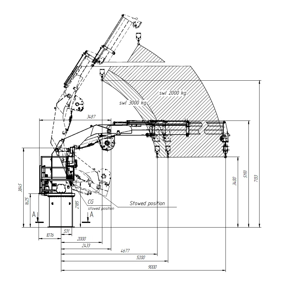
The KMU 2TX8M model features a three-section telescopic boom with an outreach ranging from 2 to 8 m. This design ensures stable and reliable operation when handling loads ranging from 2 to 3 t. Additional advantages of the model include continuous 360° slewing and a remote control pendant, significantly enhancing operational convenience and efficiency.
Loading model
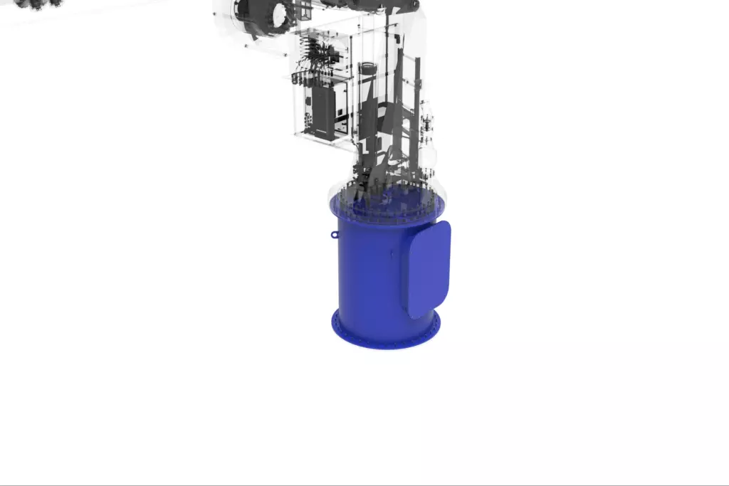
(highlighted in blue)
The robust welded base provides secure mounting of the crane slewing system. The structure is bolted to a 1.5 m high ship foundation, ensuring operational stability and safety.
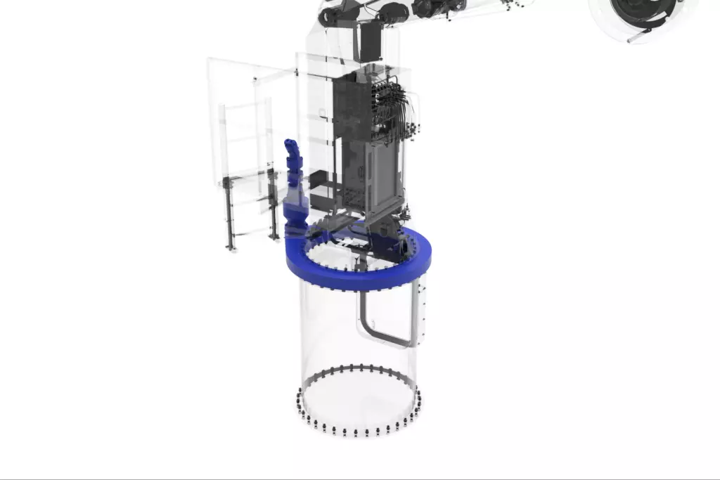
(highlighted in blue)
The driven slewing system enables continuous 360° crane rotation. The system integrates a gearbox, brake, and hydraulic motor, ensuring precise positioning and reliable operation.
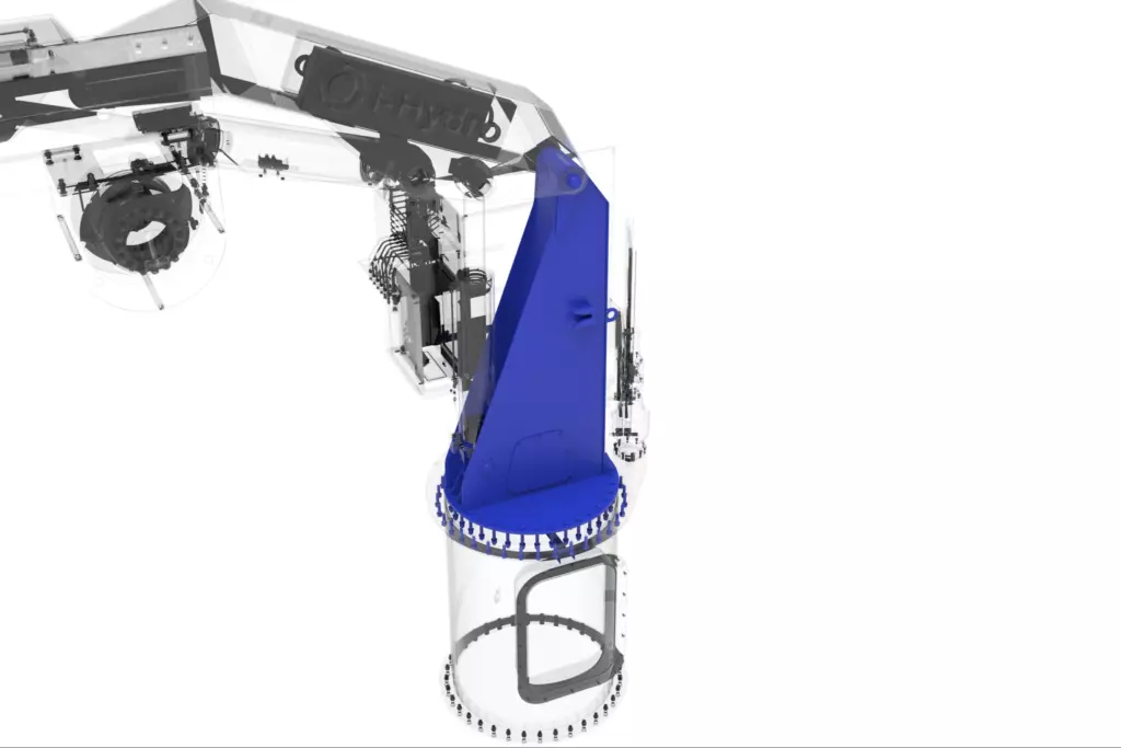
(highlighted in blue)
The robust welded column is mounted on the slewing system and serves as the primary support for the luffing section and hydraulic cylinder, ensuring overall structural stability.
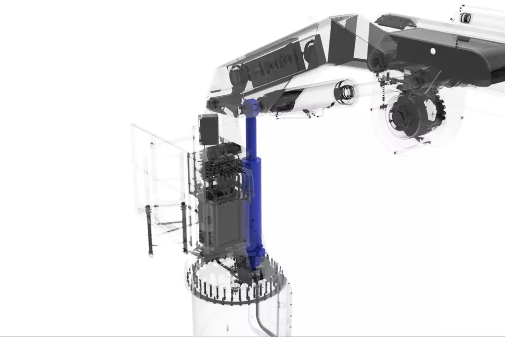
(highlighted in blue)
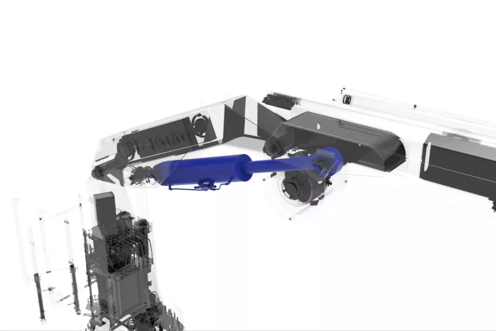
The luffing section hydraulic cylinder ensures precise adjustment of the boom outreach. Equipped with a counterbalance valve, it ensures reliable load holding under all operating conditions, including lateral loads. Manual operation of the counterbalance valve allows safe emergency lowering of the boom under its own weight in the event of power loss.
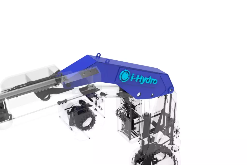
(highlighted in blue)
The luffing section enables folding of the crane into its stowed position, adjustment of the boom outreach, and ensures maximum lifting height. It is articulated to the column and serves as the mounting base for the hydraulic cylinder, telescopic section, and telescopic extension cylinder.
(highlighted in blue)
The telescopic section extension cylinder ensures boom outreach adjustment and deploys the crane into its operating position. Equipped with a counterbalance valve, it ensures reliable load holding under all operating conditions, including lateral loads. Manual operation of the counterbalance valve allows safe emergency lowering of the boom under its own weight in the event of power loss.
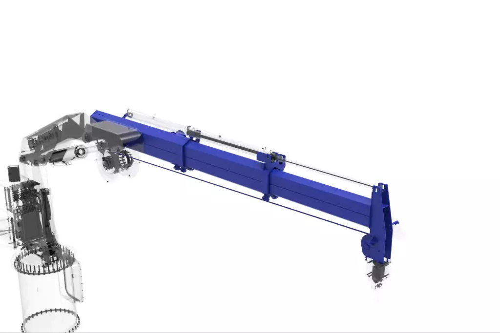
(highlighted in blue)
The three-section telescopic design (one fixed section and two movable sections) provides adjustment of outreach and hook lifting height. Dedicated mounts for two hydraulic cylinders ensure precise and reliable extension of the sections.
(highlighted in blue)
The hydraulic cylinders provide sequential and reliable extension of the telescopic sections. The cylinder design with counterbalance valves ensures safe load holding in emergency and abnormal operating conditions.
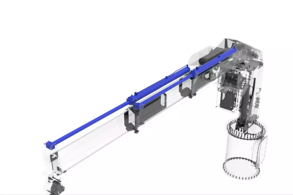
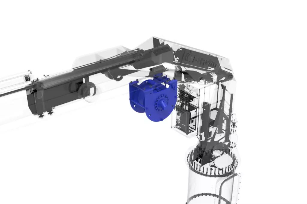
(highlighted in blue)
The winch equipped with a geared motor and a normally closed brake provides safe hoisting operation. The design includes a pressure roller for proper wire rope spooling and a rope payout limit switch, ensuring reliable operation.
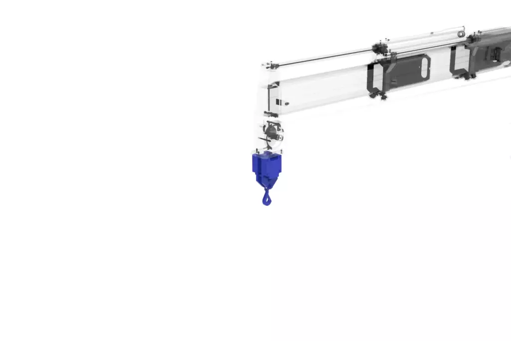
(highlighted in blue)
The hook block ensures secure load attachment via a wire rope thimble and a hook equipped with a safety latch and swivel. The robust structure ensures durability and operational safety.
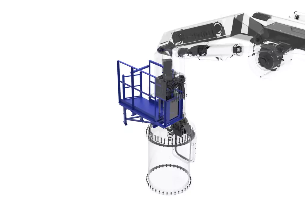
(highlighted in blue)
The operator platform, featuring an integrated local control station, is rigidly mounted on the crane column. The platform includes guardrails and an access ladder, ensuring safe and convenient working conditions.
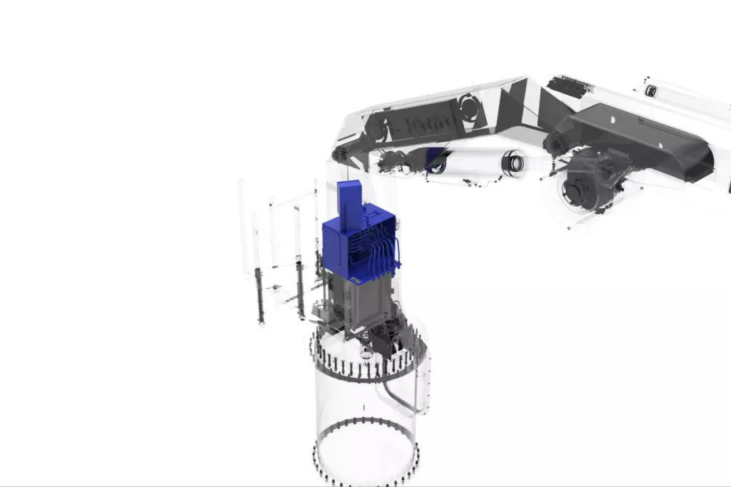
(highlighted in blue)
The local control station mounted on the slewing column provides direct control of all crane operating movements via hydraulic control valve levers and pushbuttons. An integrated control cabinet with a PLC ensures precise and reliable operation.
The following documentation provided with the crane:
| Document | Quantity |
|---|---|
| Product Data Sheet | 1 |
| Installation and Operation Manual | 1 |
| Onboard Test Program and Methodology | 1 |
| Factory Acceptance Test (FAT) Report | 1 |
| Spare Parts and Tools List | 1 |
Built with the Strength of a Giant: The Anatomy of a Knuckle Boom Marine Crane
A seaport or a vessel’s deck is a place where every centimeter and every kilogram counts. But how do you lift a three-ton container from a barge or load supplies into the hold when there’s no room on deck for a massive shore crane? The answer is simple and elegant: you need an «arm» that can fold. What we have here is an electro-hydraulic marine knuckle boom crane — a true transformer — capable of reaching 8 meters out to the water when deployed, and folding into a compact, stowed unit that stays out of the way when the vessel is battling heavy seas.
Why It’s More Complex Than It Seems
The main challenge for any marine equipment is the extreme environment. A land-based crane operates on a solid foundation, while its offshore counterpart must perform under constant vessel motion. Saltwater, wind, vibration, and continuous heel are its natural habitat. The engineers had to design a mechanism that operates reliably at temperatures down to –30 °C, withstands hurricane-force winds up to 57 m/s in the stowed position, and still ensures load retention at a vessel heel of 5 degrees. Add to that a variable outreach ranging from 2 to 8 meters and a safe working load (SWL) of up to 3 tonnes — and you have a true engineering challenge.
What it’s Made Of
Visually, the crane resembles the arm of a humanoid robot from a sci-fi movie. At its core is high-strength structural steel grade 09G2S, widely used in shipbuilding for its excellent weldability, low-temperature toughness, and ability to withstand extreme loads. Critical components such as pins and joints are manufactured from even stronger alloy steel 40X. The structure is not monolithic but modular by design. A heavy-duty base frame is bolted securely to the deck. Mounted on it is the slewing system — the crane’s «hip» — which allows continuous 360-degree rotation. Above it are the column, the main lifting boom, and finally the telescopic extension — the extendable «forearm».
How It Is Controlled
Power is provided by hydraulics. A standalone hydraulic reservoir contains AUP oil — the «lifeblood» of the system. Pressurized up to 28 MPa, the oil flows through rigid piping and high-pressure flexible hoses to the hydraulic cylinders that actuate the boom sections. Lifting operations are performed by a winch with a geared motor, while a dedicated braking system ensures the load is securely held even in the event of a power loss.
All of this is managed electronically. The operator can stand on a dedicated platform mounted on the crane or use a portable remote control to position themselves closer to the load for maximum visibility and precision. The safety system functions like a fighter jet’s autopilot: it continuously monitors lifting capacity to prevent overload. For example, if an attempt is made to lift a 3-ton load at an outreach exceeding 5.2 meters, the system will automatically inhibit the operation, protecting the crane structure from damage.
Two-in-one: Operating and Stowed Positions
The most interesting transformation happens when the job is done. The crane that has just been smoothly handling cargo must now be secured. All hydraulic cylinders retract, the telescopic boom is fully retracted, and the hook is drawn tight against the main structure by the winch. The long «arm» becomes a compact unit. In this stowed position, the crane occupies minimal deck space, is less exposed to corrosion, and is ready to withstand even the heaviest seas — ensuring that when conditions improve, it can return to operation immediately.
| Parameter | Value |
|---|---|
| Safe Working Load (SWL), min., kg max.,kg | 2000 kg; (at 8 m outreach) 3000 kg; (at 5.2 m outreach) |
| Boom outreach, m | 2 m…8 m |
| Hoisting / lowering speed, m/min | ≥ 10 m/min |
| Lowering depth, m | up to 25 m |
| Winch drive type | Hydraulic |
| Slewing angle, ° | 360° continuous |
| Slewing speed (no load), rpm | ≥ 1 rpm |
| Crane control | Local control station (on the slewing column) + remote control pendant (wired) |
| Power supply | 3-phase, 380 V, 50 Hz |
| Crane weight, kg | 5200 kg |
| Operating conditions | – Ambient temperature: –30 °C to +25 °C – Heel: up to 5° (either side) – Trim: up to 2° (bow or stern) – Wind pressure ≤ 400 Pa – Vessel-induced vibrations |
| Operating conditions (Stowed Position) | – Ambient temperature: –40 °C to +45 °C – Heel: up to 15° (either side) – Trim: up to 5° (bow or stern) – Wind pressure ≤ 2000 Pa – Vessel-induced vibrations |
The equipment complies with the following requirements:
Related
Categories & Industries
Personal Data Processing Policy
1. General provisions
This Personal data processing Policy is compiled in accordance with the requirements of Federal Law No. 152-FZ dated 27.07.2006 “On Personal Data” (hereinafter referred to as the Personal Data Law) and defines the procedure for processing personal data and measures to ensure the security of personal data taken by Izhora Hydrosystems Co. Ltd (hereinafter referred to as the Operator).
1.1. The Operator sets as its most important goal and condition for the implementation of its activities the observance of the rights and freedoms of man and citizen in the processing of his personal data, including the protection of the rights to privacy, personal and family secrets.
1.2. This Operator’s policy regarding the processing of personal data (hereinafter referred to as the Policy) applies to all information that the Operator can receive about website visitors https://i-hydro.ru .
2. Basic concepts used in the Policy
2.1. Automated processing of personal data — processing of personal data using computer technology.
2.2. Blocking of personal data — temporary termination of processing of personal data (except in cases where processing is necessary to clarify personal data).
2.3. Website – a set of graphic and informational materials, as well as computer programs and databases that ensure their availability on the Internet at a network address https://i-hydro.ru .
2.4. Personal data information system — a set of personal data contained in databases and information technologies and technical means that ensure their processing.
2.5. Depersonalization of personal data — actions as a result of which it is impossible to determine, without the use of additional information, the identity of personal data to a specific User or other subject of personal data.
2.6. Personal data processing — any action (operation) or set of actions (operations) performed with or without the use of automation tools with personal data, including collection, recording, systematization, accumulation, storage, clarification (updating, modification), extraction, use, transfer (distribution, provision, access), depersonalization, blocking, deletion, destruction of personal data.
2.7. Operator — a state body, municipal body, legal entity or individual, independently or jointly with other persons organizing and /or processing personal data, as well as determining the purposes of processing personal data, the composition of personal data to be processed, actions (operations) performed with personal data.
2.8. Personal data — any information related directly or indirectly to a specific or identifiable User of the Website https://i-hydro.ru .
2.9. Personal data authorized by the subject of personal data for distribution — personal data to which an unlimited number of persons have access by the subject of personal data by giving consent to the processing of personal data authorized by the subject of personal data for distribution in accordance with the procedure provided for by the Law on Personal Data (hereinafter — personal data authorized for distribution).
2.10. User — any visitor to the website https://i-hydro.ru .
2.11. Provision of personal data — actions aimed at disclosure of personal data to a certain person or a certain circle of persons.
2.12. Dissemination of personal data — any actions aimed at disclosure of personal data to an indefinite circle of persons (transfer of personal data) or familiarization with personal data of an unlimited circle of persons, including the publication of personal data in the media, placement in information and telecommunications networks or providing access to personal data in any other way.
2.13. Cross—border transfer of personal data is the transfer of personal data to the territory of a foreign state to the authority of a foreign state, a foreign individual or a foreign legal entity.
2.14. Destruction of personal data — any actions as a result of which personal data is permanently destroyed with the impossibility of further restoration of the content of personal data in the personal data information system and/or the material carriers of personal data are destroyed.
3. Basic rights and obligations of the Operator
3.1. The Operator has the right to:
— receive reliable information and/or documents containing personal data from the subject of personal data;
— if the personal data subject withdraws consent to the processing of personal data, as well as sending a request to terminate the processing of personal data, the Operator has the right to continue processing personal data without the consent of the personal data subject if there are grounds specified in the Law on Personal Data;
— independently determine the composition and list of measures necessary and sufficient to ensure the fulfillment of obligations provided for by the Law on Personal Data and regulatory legal acts adopted in accordance with it, unless otherwise provided by the Law on Personal Data or other federal laws.
3.2. The Operator is obliged to:
— to provide the subject of personal data, at his request, with information concerning the processing of his personal data;
— organize the processing of personal data in accordance with the procedure established by the current legislation of the Russian Federation;
— respond to requests and requests from personal data subjects and their legal representatives in accordance with the requirements of the Personal Data Law;
— to inform the authorized body for the protection of the rights of personal data subjects at the request of this body of the necessary information within 10 days from the date of receipt of such a request;
— publish or otherwise provide unrestricted access to this Policy regarding the processing of personal data;
— take legal, organizational and technical measures to protect personal data from unauthorized or accidental access to them, destruction, modification, blocking, copying, provision, dissemination of personal data, as well as from other illegal actions with respect to personal data;
— stop the transfer (distribution, provision, access) of personal data, stop processing and destroy personal data in the manner and cases provided for by the Law on Personal Data;
— perform other duties provided for by the Law on Personal Data.
4. Basic rights and obligations of personal data subjects
4.1. Personal data subjects have the right to:
— receive information concerning the processing of his personal data, except in cases provided for by federal laws. The information is provided to the personal data subject by the Operator in an accessible form, and it should not contain personal data related to other personal data subjects, except in cases where there are legitimate grounds for disclosure of such personal data. The list of information and the procedure for obtaining it is established by the Law on Personal Data;
— require the operator to clarify his personal data, block or destroy them if the personal data are incomplete, outdated, inaccurate, illegally obtained or are not necessary for the stated purpose of processing, as well as take measures provided by law to protect their rights;
— to put forward a condition of prior consent when processing personal data in order to promote goods, works and services on the market;
— to revoke consent to the processing of personal data, as well as to send a request to terminate the processing of personal data;
— appeal to the authorized body for the protection of the rights of personal data subjects or in court against illegal actions or inaction of the Operator when processing his personal data;
— to exercise other rights provided for by the legislation of the Russian Federation.
4.2. Personal data subjects are obliged to:
— provide the Operator with reliable data about themselves;
— inform the Operator about the clarification (update, change) of their personal data.
4.3. Persons who have provided the Operator with false information about themselves or information about another personal data subject without the latter’s consent are liable in accordance with the legislation of the Russian Federation.
5. Principles of personal data processing
5.1. The processing of personal data is carried out on a legal and fair basis.
5.2. The processing of personal data is limited to the achievement of specific, predetermined and legitimate goals. Processing of personal data incompatible with the purposes of personal data collection is not allowed.
5.3. It is not allowed to combine databases containing personal data, the processing of which is carried out for purposes incompatible with each other.
5.4. Only personal data that meet the purposes of their processing are subject to processing.
5.5. The content and volume of the processed personal data correspond to the stated purposes of processing. Redundancy of the processed personal data in relation to the stated purposes of their processing is not allowed.
5.6. When processing personal data, the accuracy of personal data, their sufficiency, and, if necessary, relevance to the purposes of personal data processing is ensured. The Operator takes the necessary measures and/or ensures that they are taken to delete or clarify incomplete or inaccurate data.
5.7. The storage of personal data is carried out in a form that allows determining the subject of personal data, no longer than the purposes of personal data processing require, unless the storage period of personal data is established by federal law, an agreement to which the subject of personal data is a party, beneficiary or guarantor. The processed personal data is destroyed or depersonalized upon achievement of the processing goals or in case of loss of the need to achieve these goals, unless otherwise provided by federal law.
| Purpose of processing | Informing the User by means of voice communication and e-mail |
|---|---|
| Personal data |
|
| Legal grounds |
|
| Types of personal data processing |
|
7. Terms of personal data processing
7.1. The processing of personal data is carried out with the consent of the personal data subject to the processing of his personal data.
7.2. The processing of personal data is necessary to achieve the goals stipulated by an international agreement of the Russian Federation or a law, to carry out the functions, powers and duties assigned to the operator by the legislation of the Russian Federation.
7.3. The processing of personal data is necessary for the administration of justice, the execution of a judicial act, an act of another body or official subject to execution in accordance with the legislation of the Russian Federation on enforcement proceedings.
7.4. The processing of personal data is necessary for the execution of a contract to which the personal data subject is a party or beneficiary or guarantor, as well as for the conclusion of a contract on the initiative of the personal data subject or a contract under which the personal data subject will be a beneficiary or guarantor.
7.5. The processing of personal data is necessary to exercise the rights and legitimate interests of the operator or third parties or to achieve socially significant goals, provided that the rights and freedoms of the personal data subject are not violated.
7.6. Personal data is processed, access to which is granted to an unlimited number of persons by the subject of personal data or at his request (hereinafter referred to as publicly available personal data).
7.7. Personal data subject to publication or mandatory disclosure in accordance with federal law is processed.8. Procedure for the collection, storage, transfer and other types of personal data processing
The security of personal data processed by the Operator is ensured through the implementation of legal, organizational and technical measures necessary to fully comply with the requirements of current legislation in the field of personal data protection.
8. Procedure for the collection, storage, transfer and other types of personal data processing
The security of personal data processed by the Operator is ensured through the implementation of legal, organizational and technical measures necessary to fully comply with the requirements of current legislation in the field of personal data protection.
8.1. The Operator ensures the safety of personal data and takes all possible measures to exclude access to the personal data of unauthorized persons.
8.2. The User’s personal data will never, under any circumstances, be transferred to third parties, except in cases related to the implementation of current legislation or if the subject of personal data has given consent to the Operator to transfer data to a third party to fulfill obligations under a civil contract.
8.3. In case of inaccuracies in personal data, the User can update them independently by sending a notification to the Operator to the Operator’s email address
contact@i-hydro.ru
8.4. The period of processing of personal data is determined by the achievement of the purposes for which personal data was collected, unless another period is provided for by the contract or current legislation..
The User can withdraw his consent to the processing of personal data at any time by sending a notification to the Operator via e-mail to the Operator’s e-mail address contact@i-hydro.ru marked “Withdrawal of consent to the processing of personal data”.
8.5. All information collected by third-party services, including payment systems, means of communication and other service providers, is stored and processed by these persons (Operators) in accordance with their User Agreement and Privacy Policy. The subject of personal data and/or with the specified documents. The Operator is not responsible for the actions of third parties, including the service providers specified in this paragraph.
8.6. The prohibitions established by the subject of personal data on the transfer (except for granting access), as well as on the processing or processing conditions (except for obtaining access) of personal data permitted for distribution, do not apply in cases of processing of personal data in the state, public and other public interests defined by the legislation of the Russian Federation.
8.7. When processing personal data, the Operator ensures the confidentiality of personal data.
8.8. The Operator stores personal data in a form that allows determining the subject of personal data, no longer than the purposes of personal data processing require, unless the period of personal data storage is established by federal law, an agreement to which the subject of personal data is a party, beneficiary or guarantor.
8.9. The condition for the termination of personal data processing may be the achievement of the purposes of personal data processing, the expiration of the consent of the personal data subject, the withdrawal of consent by the personal data subject or the requirement to terminate the processing of personal data, as well as the identification of unlawful processing of personal data.
9. List of actions performed by the Operator with the received personal data
9.1. The Operator collects, records, systematizes, accumulates, stores, clarifies (updates, changes), extracts, uses, transfers (distribution, provision, access), depersonalizes, blocks, deletes and destroys personal data.
9.2. The Operator performs automated processing of personal data with or without receiving and/or transmitting the received information via information and telecommunication networks.
10. Cross-border transfer of personal data
10.1. Prior to the start of cross-border transfer of personal data, the Operator is obliged to notify the authorized body for the protection of the rights of personal data subjects of its intention to carry out cross-border transfer of personal data (such notification is sent separately from the notification of the intention to process personal data).
10.2. Before submitting the above notification, the Operator is obliged to receive relevant information from the authorities of a foreign state, foreign individuals, foreign legal entities to whom the cross-border transfer of personal data is planned.
11. Confidentiality of personal data
The operator and other persons who have gained access to personal data are obliged not to disclose to third parties and not to distribute personal data without the consent of the subject of personal data, unless otherwise provided by federal law.
12. Final provisions
12.1. The User can receive any clarifications on issues of interest concerning the processing of his personal data by contacting the Operator via e-mail
contact@i-hydro.ru
12.2. This document will reflect any changes to the personal data processing policy by the Operator. The policy is valid indefinitely until it is replaced by a new version.
12.3. The current version of the Policy is freely available on the Internet at https://i-hydro.ru .