Navigation
Related
Categories & Industries

The static load hydraulic test stand, developed for KSTU (Kaliningrad State Technical University), is an integrated software and hardware solution designed for structural testing of complex shipbuilding components. The test stand is designed to simulate real-world stresses on large-scale models and hull sections — including bottom plating, frames, keels, rods, and other load-bearing structures — while capturing high-precision data on component behavior under load.
Shipbuilding demands the highest standards of structural integrity, as a design error can be extremely costly. To ensure a hull can withstand real-world stresses, engineers test its components at the prototype stage: they apply loads, induce deformations, and push materials to their limits — all within a controlled laboratory environment providing precise data. This process identifies structural deformation long before the vessel ever touches the water. The “Hydrostand” complex was specifically engineered to meet these demanding requirements.
The Kaliningrad State Technical University required a modernization of such equipment: the legacy test rig was in need of repair, and its capabilities no longer met the contemporary demands of the shipbuilding laboratory. The challenge was ambitious:
Click an item to navigate through the article
Experts from «Izhora Hydrosystems» developed the complex in strict accordance with the client’s specifications and operational requirements.
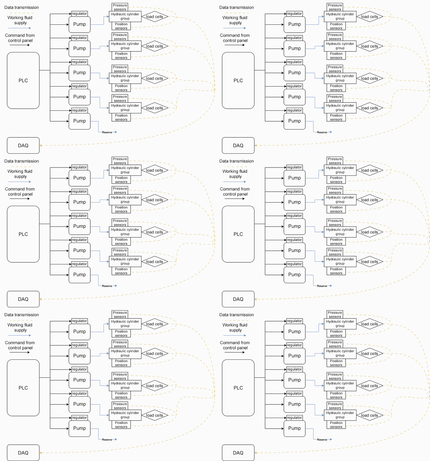
At the core of the test stand is an integrated hardware and software control system featuring a multi-level architecture: local and remote control stations, a Linux-based PC, a Programmable Logic Controller (PLC), and a dedicated Data Acquisition and Processing System (DAPS).
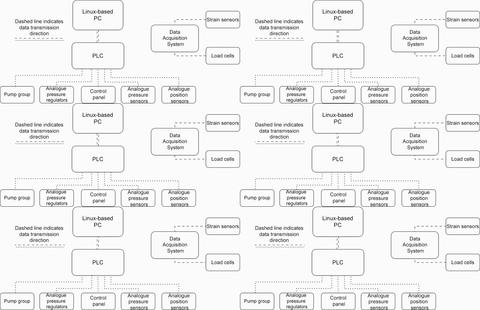

One of the primary requirements was the ability to conduct tests in a fully automated mode based on predefined algorithms. How was this achieved?
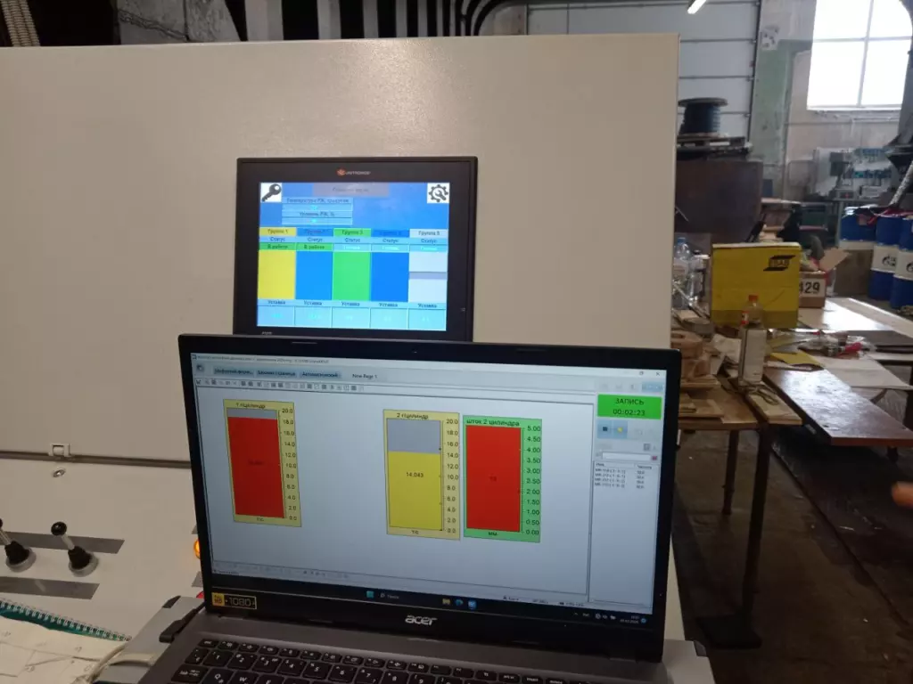
The operator pre-configures the testing sequence using specialized software installed on the control PC. This allows for setting target pressures for each group of hydraulic cylinders with an increment of 0.5 bar and a 1-second resolution, defining time intervals and, if necessary, setting specific force levels to maintain the specimen under static load for a predetermined duration. The finalized loading algorithm is converted into specific PLC commands and executed automatically by the system, ensuring zero operator intervention and strict adherence to the test plan. This is particularly critical for long-duration cyclic tests, where human factors could introduce inaccuracies into the testing cycle.
For tasks requiring greater flexibility, the operator can manage the pressure in each of the four hydraulic cylinder groups independently. Furthermore, if the test specimen has a complex geometry, individual cylinder displacement within a single group can be controlled separately. This functionality allows for precise positioning of the hydraulic cylinders to match the specimen’s shape prior to executing the automated algorithm or for performing basic manual load tests. All control functions are accessible via both the local control station and the remote control unit.
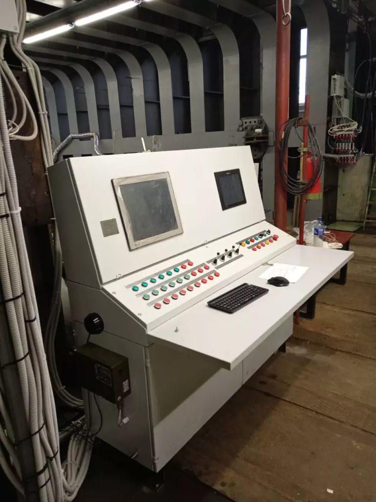
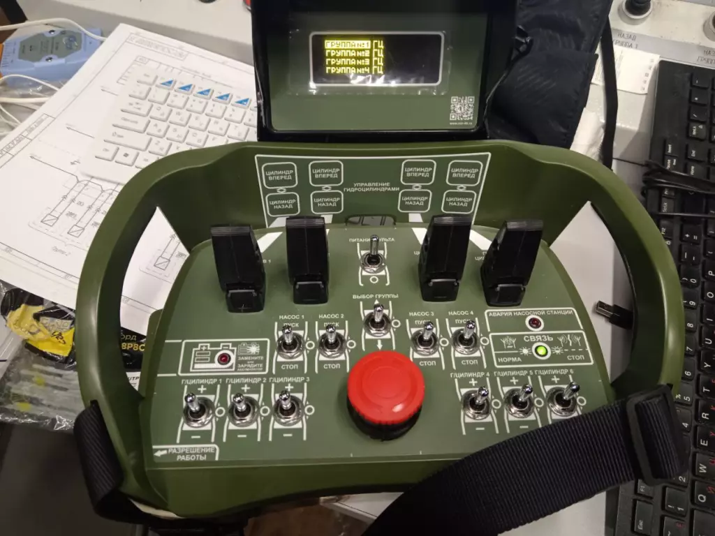
An important distinction: the control stations themselves are not measuring instruments. To ensure data integrity, the system utilizes a DAPS — a certified unit included in the State Register of Measuring Instruments. This system interfaces with four types of sensors: load cells, strain gauges, displacement sensors, and pressure sensors. Data is transmitted to a dedicated PC that remains fundamentally independent of the control loop. The DAPS includes specialized software for data acquisition and processing, enabling real-time load charting and comprehensive documentation of all sensor readings. This provides a complete overview of the test for subsequent analysis and reporting.
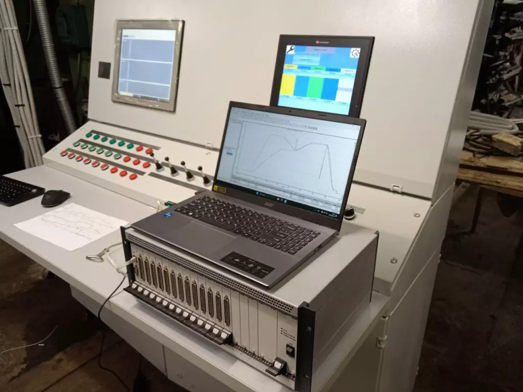
An important distinction: the control stations themselves are not measuring instruments. To ensure data integrity, the system utilizes a DAPS — a certified unit included in the State Register of Measuring Instruments. This system interfaces with four types of sensors: load cells, strain gauges, displacement sensors, and pressure sensors. Data is transmitted to a dedicated PC that remains fundamentally independent of the control loop. The DAPS includes specialized software for data acquisition and processing, enabling real-time load charting and comprehensive documentation of all sensor readings. This provides a complete overview of the test for subsequent analysis and reporting.
The control system dictates the parameters — but what provides the direct physical force on the specimen?
If the control system is the brain of the complex, then the hydraulic cylinders are its muscles. They convert hydraulic pressure into the mechanical force applied directly to the test specimen. Following the KSTU technical specifications, three types of hydraulic cylinders were developed:
All cylinder types feature a 500 mm stroke. The system supports the simultaneous connection of up to 24 hydraulic cylinders, divided into four independent groups.
The rod end of each cylinder is threaded to allow for the attachment of a load cell and/or an extension rod. This provides the flexibility to adapt the configuration to the specific geometry of the test specimen. The cylinders are secured to the test stand frame via two base plates using bolted connections.
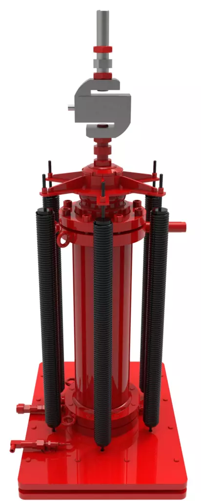
Available in two versions — 20 and 50 tons. These cylinders exert load in one direction only (extension). An enhanced return mechanism allows the cylinder to be operated in various planes and at different angles. This design ensures increased reliability and stability under real-world operating conditions. This is particularly critical when testing complex hull structures, where load application points are not always vertically aligned.
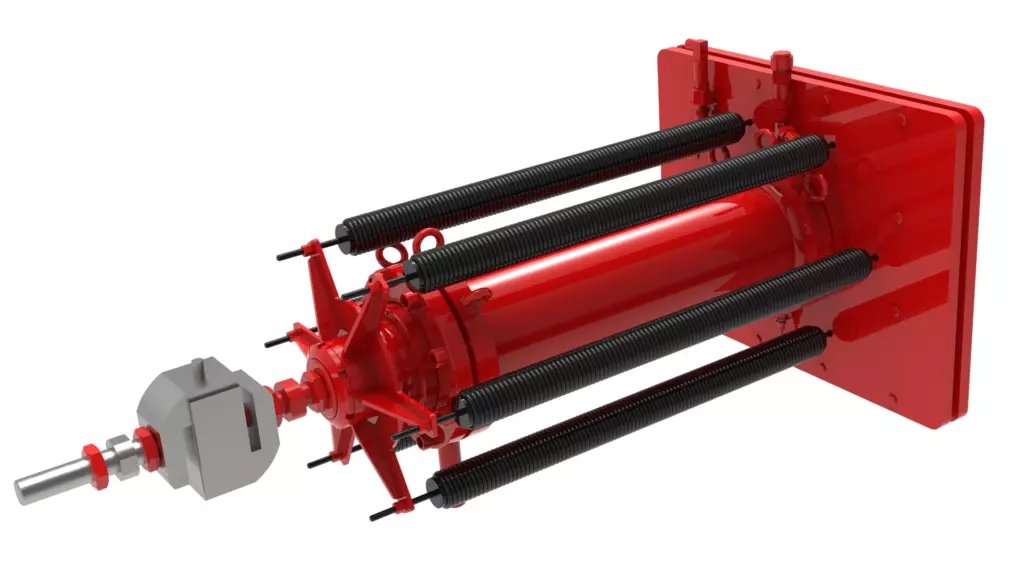
Available in two versions — 20 and 50 tons. These cylinders exert load in one direction only (extension). An enhanced return mechanism allows the cylinder to be operated in various planes and at different angles. This design ensures increased reliability and stability under real-world operating conditions. This is particularly critical when testing complex hull structures, where load application points are not always vertically aligned.
Available in versions up to 20 tons. Their fundamental advantage is the ability to exert load in both directions: extension and retraction. This enables tensile testing of structural elements — for example, analyzing how a frame or a bracket performs under multi-directional loads.
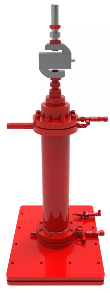
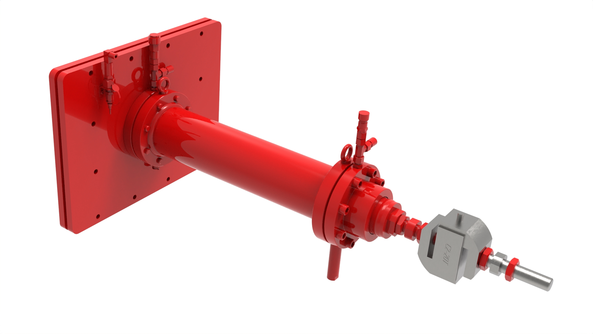
Available in versions up to 20 tons. Their fundamental advantage is the ability to exert load in both directions: extension and retraction. This enables tensile testing of structural elements — for example, analyzing how a frame or a bracket performs under multi-directional loads.
Setting the precise pressure is only half the task. It is also essential to ensure that the actuators perform exactly as prescribed. How is this achieved?
Each hydraulic cylinder is equipped with two sensors. An integrated magnetostrictive position sensor tracks rod displacement and transmits data to the PLC. It forms the basis for precise manual control.. An oil pressure transmitter (RPD-I) is installed on each cylinder to monitor the hydraulic fluid pressure entering the chamber. This data is also fed into the PLC, providing necessary feedback for the analog pressure regulators. Readings from both sensors are displayed on the operator’s screen in real time.
But how can we be certain that the system pressure truly corresponds to the force being transmitted to the specimen?
A dedicated load cell is mounted at the rod end. It measures the actual force applied directly to the specimen rather than the internal system pressure. These sensors are matched to the actual cylinder capacities: with a resolution of 10 N for 20-ton cylinders and 25 N for 50-ton cylinders. Data from the load cells is transmitted directly to the DAPS, where it is used to generate real-time loading charts.
Hydraulic cylinders generate force equal to the product of the piston’s effective area and the supplied pressure — but where does this pressure originate?
The HPU is an autonomous system; without it, the entire complex remains stationary. It supplies all hydraulic components of the stand with hydraulic fluid at the required pressure, while simultaneously monitoring temperature and cleanliness. The HPU consists of a pump unit, a hydraulic tank, a cooling system, and a filtration system with pressure lines.
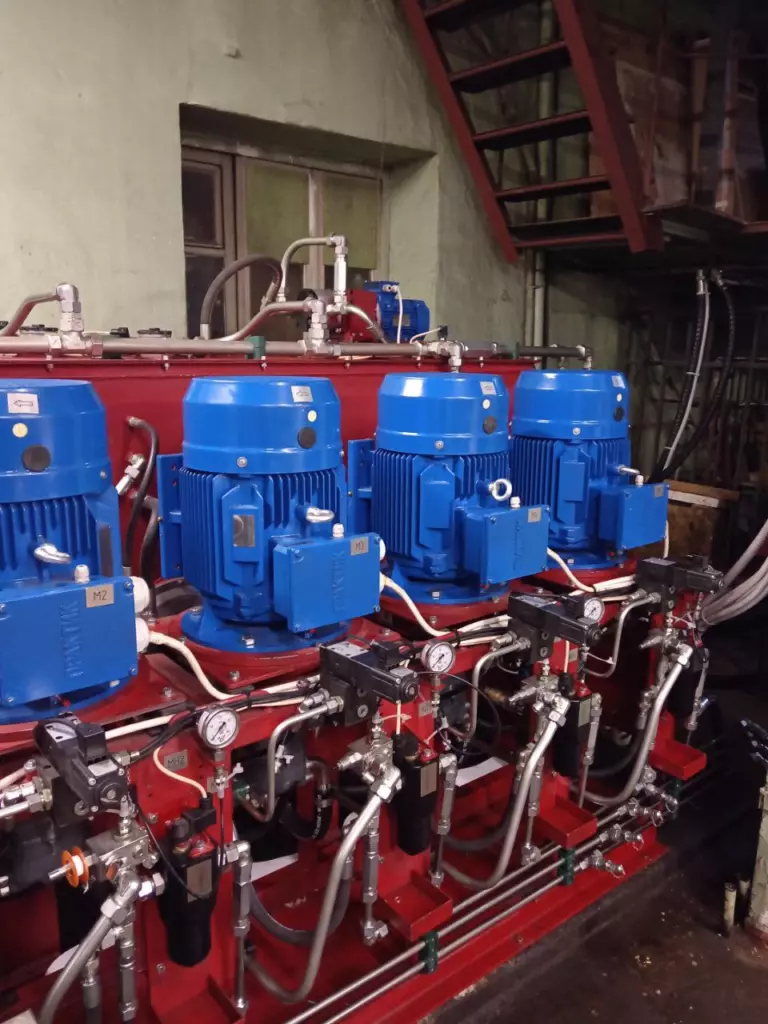
The pump unit consists of four main pumps and a fifth standby pump. This configuration eliminates downtime in the event of a single pump failure. Each pump is driven by its own dedicated electric motor.
Each pump generates pressure up to 200 bar, supplying hydraulic fluid to its respective pressure line through high-pressure filters. One line services a group of up to six hydraulic cylinders, allowing the entire unit to manage 24 cylinders across four independent groups. If a line is not fully populated with cylinders, the system can isolate and block the fluid supply to the unused pressure ports. In the event of a switch to the standby pump, this can be performed directly from the control station — each pressure line can be cross-connected to any of the pumps.
Each pump generates pressure up to 200 bar, supplying hydraulic fluid to its respective pressure line through high-pressure filters. One line services a group of up to six hydraulic cylinders, allowing the entire unit to manage 24 cylinders across four independent groups. If a line is not fully populated with cylinders, the system can isolate and block the fluid supply to the unused pressure ports. In the event of a switch to the standby pump, this can be performed directly from the control station — each pressure line can be cross-connected to any of the pumps.
What if the design requires non-uniform loading, such as applying different pressures to various sections of the hull?
The pump continuously maintains maximum pressure at the proportional valve inlet. Based on the PLC command, the valve reduces this pressure to the operator-defined level in 0.5 bar increments. Pressure is regulated independently for each group, enabling non-uniform loading on the specimen — a feature critical for testing structures with complex geometries. If a piston cylinder is connected to the directional control valve, the system can route the hydraulic fluid to either the piston or the rod chamber, depending on the required force direction.
The 2,000-liter hydraulic tank serves for fluid accumulation and thermal stabilization, ensuring the steady operation of the test stand across all duty cycles.
Filling is performed via a dedicated circuit equipped with an electric motor-driven pump. Before entering the tank, the oil passes through coarse filters to prevent mechanical contaminants from entering the system.
The tank is equipped with fluid temperature sensors that transmit signals to the PLC for monitoring and managing the thermal conditions of the hydraulic fluid.
Hydraulic oil heats up during operation, which is normal within certain limits. The system’s operating temperature range is between −15 and +40 °C. Once the fluid temperature exceeds +45 °C, the PLC automatically activates the cooling system. If the temperature reaches +60 °C, the test stand performs a full emergency shutdown.
The cooling system operates as follows: a cooling pump, driven by an electric motor, generates pressure to circulate hot fluid from the tank through the oil cooler (heat exchanger) and back. The oil cooler is a standalone radiator equipped with a fan, providing a heat dissipation capacity of 7.2 kW. It must be installed in a location with a constant supply of fresh air to ensure maximum efficiency.
«Izhora Hydrosystems» is more than just a supplier of hydraulic equipment. The company specializes in developing sophisticated hardware and software complexes powered by hydraulics: ranging from custom hydraulic power units to multi-cylinder test stands with proprietary control and measurement systems. The test stand developed for KSTU is a clear example of this approach: the customer received a unified, turnkey solution engineered from the ground up for specific objectives.
The Russian market features many manufacturers of testing equipment, yet most offer either universal solutions for standardized components or stands with a limited number of loading points and basic control systems. Such equipment is suitable for standard tasks but falls short when it is necessary to simultaneously manage dozens of hydraulic cylinders divided into independent groups, monitor actual force at every point, and execute complex loading algorithms in an automated mode.
And finally — all of this is built on domestic equipment, backed by comprehensive support.
This is where the testing complex by «Izhora Hydrosystems» stands out. Managing 24 hydraulic cylinders across four independent groups, precision pressure regulation with 0.5 bar increments, a certified DAPS supporting four types of sensors, and a fully automated testing mode based on custom scenarios — all realized within a single domestically produced complex. Independence from foreign component suppliers and comprehensive technical support make this solution resilient under current import restrictions. Confidence in the system’s reliability is further backed by warranty obligations: the test stand is covered by an 18-month storage and 24-month operational warranty, while the hydraulic cylinders carry a 12-month operational warranty.
Related
Categories & Industries
Personal Data Processing Policy
1. General provisions
This Personal data processing Policy is compiled in accordance with the requirements of Federal Law No. 152-FZ dated 27.07.2006 “On Personal Data” (hereinafter referred to as the Personal Data Law) and defines the procedure for processing personal data and measures to ensure the security of personal data taken by Izhora Hydrosystems Co. Ltd (hereinafter referred to as the Operator).
1.1. The Operator sets as its most important goal and condition for the implementation of its activities the observance of the rights and freedoms of man and citizen in the processing of his personal data, including the protection of the rights to privacy, personal and family secrets.
1.2. This Operator’s policy regarding the processing of personal data (hereinafter referred to as the Policy) applies to all information that the Operator can receive about website visitors https://i-hydro.ru .
2. Basic concepts used in the Policy
2.1. Automated processing of personal data — processing of personal data using computer technology.
2.2. Blocking of personal data — temporary termination of processing of personal data (except in cases where processing is necessary to clarify personal data).
2.3. Website – a set of graphic and informational materials, as well as computer programs and databases that ensure their availability on the Internet at a network address https://i-hydro.ru .
2.4. Personal data information system — a set of personal data contained in databases and information technologies and technical means that ensure their processing.
2.5. Depersonalization of personal data — actions as a result of which it is impossible to determine, without the use of additional information, the identity of personal data to a specific User or other subject of personal data.
2.6. Personal data processing — any action (operation) or set of actions (operations) performed with or without the use of automation tools with personal data, including collection, recording, systematization, accumulation, storage, clarification (updating, modification), extraction, use, transfer (distribution, provision, access), depersonalization, blocking, deletion, destruction of personal data.
2.7. Operator — a state body, municipal body, legal entity or individual, independently or jointly with other persons organizing and /or processing personal data, as well as determining the purposes of processing personal data, the composition of personal data to be processed, actions (operations) performed with personal data.
2.8. Personal data — any information related directly or indirectly to a specific or identifiable User of the Website https://i-hydro.ru .
2.9. Personal data authorized by the subject of personal data for distribution — personal data to which an unlimited number of persons have access by the subject of personal data by giving consent to the processing of personal data authorized by the subject of personal data for distribution in accordance with the procedure provided for by the Law on Personal Data (hereinafter — personal data authorized for distribution).
2.10. User — any visitor to the website https://i-hydro.ru .
2.11. Provision of personal data — actions aimed at disclosure of personal data to a certain person or a certain circle of persons.
2.12. Dissemination of personal data — any actions aimed at disclosure of personal data to an indefinite circle of persons (transfer of personal data) or familiarization with personal data of an unlimited circle of persons, including the publication of personal data in the media, placement in information and telecommunications networks or providing access to personal data in any other way.
2.13. Cross—border transfer of personal data is the transfer of personal data to the territory of a foreign state to the authority of a foreign state, a foreign individual or a foreign legal entity.
2.14. Destruction of personal data — any actions as a result of which personal data is permanently destroyed with the impossibility of further restoration of the content of personal data in the personal data information system and/or the material carriers of personal data are destroyed.
3. Basic rights and obligations of the Operator
3.1. The Operator has the right to:
— receive reliable information and/or documents containing personal data from the subject of personal data;
— if the personal data subject withdraws consent to the processing of personal data, as well as sending a request to terminate the processing of personal data, the Operator has the right to continue processing personal data without the consent of the personal data subject if there are grounds specified in the Law on Personal Data;
— independently determine the composition and list of measures necessary and sufficient to ensure the fulfillment of obligations provided for by the Law on Personal Data and regulatory legal acts adopted in accordance with it, unless otherwise provided by the Law on Personal Data or other federal laws.
3.2. The Operator is obliged to:
— to provide the subject of personal data, at his request, with information concerning the processing of his personal data;
— organize the processing of personal data in accordance with the procedure established by the current legislation of the Russian Federation;
— respond to requests and requests from personal data subjects and their legal representatives in accordance with the requirements of the Personal Data Law;
— to inform the authorized body for the protection of the rights of personal data subjects at the request of this body of the necessary information within 10 days from the date of receipt of such a request;
— publish or otherwise provide unrestricted access to this Policy regarding the processing of personal data;
— take legal, organizational and technical measures to protect personal data from unauthorized or accidental access to them, destruction, modification, blocking, copying, provision, dissemination of personal data, as well as from other illegal actions with respect to personal data;
— stop the transfer (distribution, provision, access) of personal data, stop processing and destroy personal data in the manner and cases provided for by the Law on Personal Data;
— perform other duties provided for by the Law on Personal Data.
4. Basic rights and obligations of personal data subjects
4.1. Personal data subjects have the right to:
— receive information concerning the processing of his personal data, except in cases provided for by federal laws. The information is provided to the personal data subject by the Operator in an accessible form, and it should not contain personal data related to other personal data subjects, except in cases where there are legitimate grounds for disclosure of such personal data. The list of information and the procedure for obtaining it is established by the Law on Personal Data;
— require the operator to clarify his personal data, block or destroy them if the personal data are incomplete, outdated, inaccurate, illegally obtained or are not necessary for the stated purpose of processing, as well as take measures provided by law to protect their rights;
— to put forward a condition of prior consent when processing personal data in order to promote goods, works and services on the market;
— to revoke consent to the processing of personal data, as well as to send a request to terminate the processing of personal data;
— appeal to the authorized body for the protection of the rights of personal data subjects or in court against illegal actions or inaction of the Operator when processing his personal data;
— to exercise other rights provided for by the legislation of the Russian Federation.
4.2. Personal data subjects are obliged to:
— provide the Operator with reliable data about themselves;
— inform the Operator about the clarification (update, change) of their personal data.
4.3. Persons who have provided the Operator with false information about themselves or information about another personal data subject without the latter’s consent are liable in accordance with the legislation of the Russian Federation.
5. Principles of personal data processing
5.1. The processing of personal data is carried out on a legal and fair basis.
5.2. The processing of personal data is limited to the achievement of specific, predetermined and legitimate goals. Processing of personal data incompatible with the purposes of personal data collection is not allowed.
5.3. It is not allowed to combine databases containing personal data, the processing of which is carried out for purposes incompatible with each other.
5.4. Only personal data that meet the purposes of their processing are subject to processing.
5.5. The content and volume of the processed personal data correspond to the stated purposes of processing. Redundancy of the processed personal data in relation to the stated purposes of their processing is not allowed.
5.6. When processing personal data, the accuracy of personal data, their sufficiency, and, if necessary, relevance to the purposes of personal data processing is ensured. The Operator takes the necessary measures and/or ensures that they are taken to delete or clarify incomplete or inaccurate data.
5.7. The storage of personal data is carried out in a form that allows determining the subject of personal data, no longer than the purposes of personal data processing require, unless the storage period of personal data is established by federal law, an agreement to which the subject of personal data is a party, beneficiary or guarantor. The processed personal data is destroyed or depersonalized upon achievement of the processing goals or in case of loss of the need to achieve these goals, unless otherwise provided by federal law.
| Purpose of processing | Informing the User by means of voice communication and e-mail |
|---|---|
| Personal data |
|
| Legal grounds |
|
| Types of personal data processing |
|
7. Terms of personal data processing
7.1. The processing of personal data is carried out with the consent of the personal data subject to the processing of his personal data.
7.2. The processing of personal data is necessary to achieve the goals stipulated by an international agreement of the Russian Federation or a law, to carry out the functions, powers and duties assigned to the operator by the legislation of the Russian Federation.
7.3. The processing of personal data is necessary for the administration of justice, the execution of a judicial act, an act of another body or official subject to execution in accordance with the legislation of the Russian Federation on enforcement proceedings.
7.4. The processing of personal data is necessary for the execution of a contract to which the personal data subject is a party or beneficiary or guarantor, as well as for the conclusion of a contract on the initiative of the personal data subject or a contract under which the personal data subject will be a beneficiary or guarantor.
7.5. The processing of personal data is necessary to exercise the rights and legitimate interests of the operator or third parties or to achieve socially significant goals, provided that the rights and freedoms of the personal data subject are not violated.
7.6. Personal data is processed, access to which is granted to an unlimited number of persons by the subject of personal data or at his request (hereinafter referred to as publicly available personal data).
7.7. Personal data subject to publication or mandatory disclosure in accordance with federal law is processed.8. Procedure for the collection, storage, transfer and other types of personal data processing
The security of personal data processed by the Operator is ensured through the implementation of legal, organizational and technical measures necessary to fully comply with the requirements of current legislation in the field of personal data protection.
8. Procedure for the collection, storage, transfer and other types of personal data processing
The security of personal data processed by the Operator is ensured through the implementation of legal, organizational and technical measures necessary to fully comply with the requirements of current legislation in the field of personal data protection.
8.1. The Operator ensures the safety of personal data and takes all possible measures to exclude access to the personal data of unauthorized persons.
8.2. The User’s personal data will never, under any circumstances, be transferred to third parties, except in cases related to the implementation of current legislation or if the subject of personal data has given consent to the Operator to transfer data to a third party to fulfill obligations under a civil contract.
8.3. In case of inaccuracies in personal data, the User can update them independently by sending a notification to the Operator to the Operator’s email address
contact@i-hydro.ru
8.4. The period of processing of personal data is determined by the achievement of the purposes for which personal data was collected, unless another period is provided for by the contract or current legislation..
The User can withdraw his consent to the processing of personal data at any time by sending a notification to the Operator via e-mail to the Operator’s e-mail address contact@i-hydro.ru marked “Withdrawal of consent to the processing of personal data”.
8.5. All information collected by third-party services, including payment systems, means of communication and other service providers, is stored and processed by these persons (Operators) in accordance with their User Agreement and Privacy Policy. The subject of personal data and/or with the specified documents. The Operator is not responsible for the actions of third parties, including the service providers specified in this paragraph.
8.6. The prohibitions established by the subject of personal data on the transfer (except for granting access), as well as on the processing or processing conditions (except for obtaining access) of personal data permitted for distribution, do not apply in cases of processing of personal data in the state, public and other public interests defined by the legislation of the Russian Federation.
8.7. When processing personal data, the Operator ensures the confidentiality of personal data.
8.8. The Operator stores personal data in a form that allows determining the subject of personal data, no longer than the purposes of personal data processing require, unless the period of personal data storage is established by federal law, an agreement to which the subject of personal data is a party, beneficiary or guarantor.
8.9. The condition for the termination of personal data processing may be the achievement of the purposes of personal data processing, the expiration of the consent of the personal data subject, the withdrawal of consent by the personal data subject or the requirement to terminate the processing of personal data, as well as the identification of unlawful processing of personal data.
9. List of actions performed by the Operator with the received personal data
9.1. The Operator collects, records, systematizes, accumulates, stores, clarifies (updates, changes), extracts, uses, transfers (distribution, provision, access), depersonalizes, blocks, deletes and destroys personal data.
9.2. The Operator performs automated processing of personal data with or without receiving and/or transmitting the received information via information and telecommunication networks.
10. Cross-border transfer of personal data
10.1. Prior to the start of cross-border transfer of personal data, the Operator is obliged to notify the authorized body for the protection of the rights of personal data subjects of its intention to carry out cross-border transfer of personal data (such notification is sent separately from the notification of the intention to process personal data).
10.2. Before submitting the above notification, the Operator is obliged to receive relevant information from the authorities of a foreign state, foreign individuals, foreign legal entities to whom the cross-border transfer of personal data is planned.
11. Confidentiality of personal data
The operator and other persons who have gained access to personal data are obliged not to disclose to third parties and not to distribute personal data without the consent of the subject of personal data, unless otherwise provided by federal law.
12. Final provisions
12.1. The User can receive any clarifications on issues of interest concerning the processing of his personal data by contacting the Operator via e-mail
contact@i-hydro.ru
12.2. This document will reflect any changes to the personal data processing policy by the Operator. The policy is valid indefinitely until it is replaced by a new version.
12.3. The current version of the Policy is freely available on the Internet at https://i-hydro.ru .